Lifting device

A hoisting device and hoisting plate technology, applied in the directions of transportation and packaging, load hoisting components, etc., can solve the problems of large workload and low efficiency in dismantling and re-installing diesel engine components, and achieve low hoisting cost and high hoisting safety. , The effect of high lifting efficiency

Pending Publication Date: 2022-01-21
CSSC POWER INST CO LTD
View PDF0 Cites 0 Cited by
  • Summary
  • Abstract
  • Description
  • Claims
  • Application Information

AI Technical Summary

Problems solved by technology

Using this lifting tool and method requires a lot of work to remove diesel engine parts and reinstall them, and the efficiency is very low

Method used


Image

  • Lifting device
  • Lifting device
  • Lifting device

Examples


Embodiment Construction

[0030] In order to make the technical problems solved by the present invention, the technical solutions adopted and the technical effects achieved clearer, the technical solutions of the embodiments of the present invention will be further described in detail below in conjunction with the accompanying drawings. Obviously, the described embodiments are only the technical solutions of the present invention. Some, but not all, embodiments. Based on the embodiments of the present invention, all other embodiments obtained by those skilled in the art without creative efforts fall within the protection scope of the present invention.

[0031] In the description of the present invention, it should be noted that the terms "center", "upper", "lower", "left", "right", "vertical", "horizontal", "inner", "outer" etc. The indicated orientation or positional relationship is based on the orientation or positional relationship shown in the drawings, and is only for the convenience of describin...


PUM


Abstract

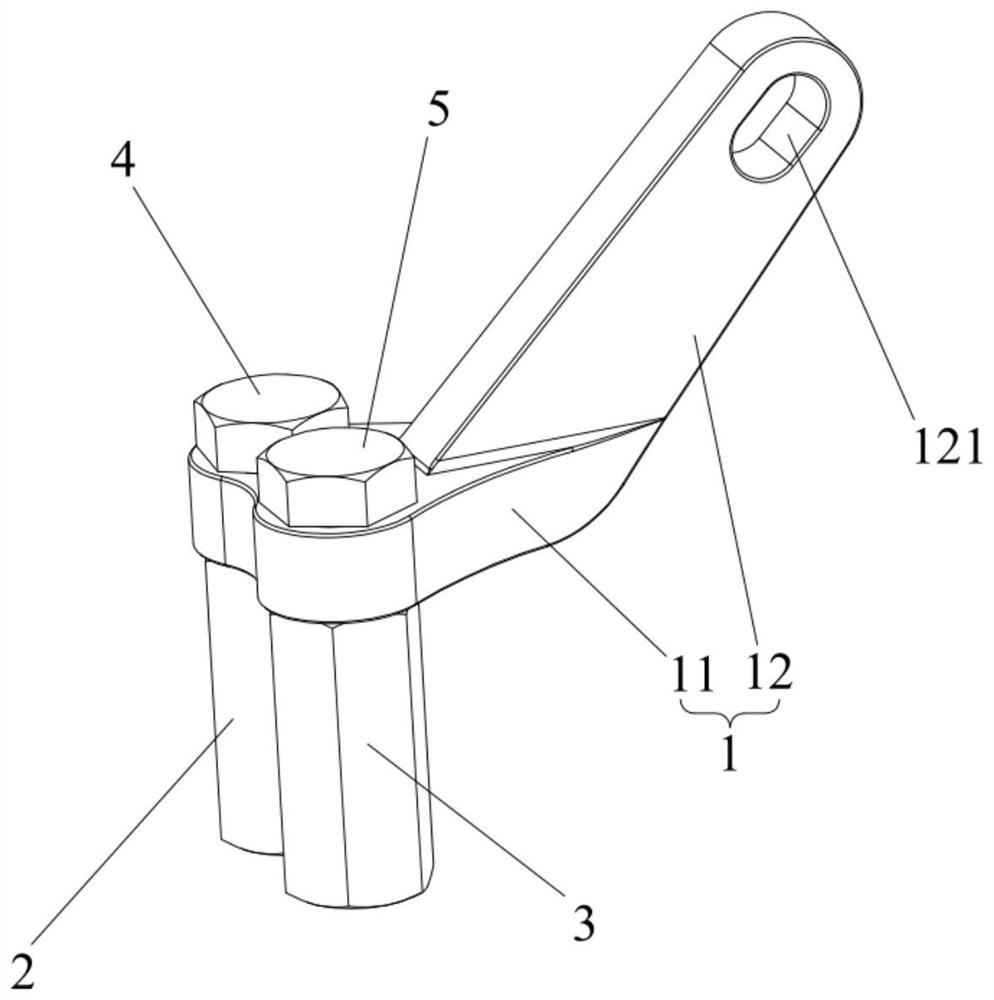
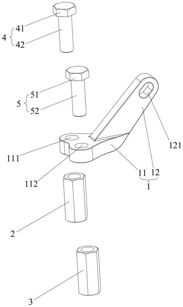
The invention relates to the technical field of lifting equipment, and discloses a lifting device. The lifting device comprises a lifting piece, a first sleeve, a second sleeve, a first fastener and a second fastener; the lifting piece comprises a lifting plate and a lifting arm which are connected; the lifting arm is used for being connected with a crane; the first sleeve is used for being in threaded connection with a first cylinder cover bolt of a cylinder cover to be lifted; the second sleeve is used for being in threaded connection with a second cylinder cover bolt of the cylinder cover to be lifted; the first fastener is used for being detachably connected with the lifting plate and the first sleeve; and the second fastener is used for being detachably connected with the lifting plate and the second sleeve. The lifting device provided by the invention has the advantages of high lifting safety, high lifting efficiency, no need of machining a lifting hole in an existing cylinder cover, adjustable lifting acting force applying position and low lifting cost.

Description

technical field [0001] The invention relates to the technical field of lifting equipment, in particular to a lifting device. Background technique [0002] The arrangement of the cylinder heads on the top of some types of low-speed diesel engines is very different from that of traditional low-speed diesel engines, which makes the layout of the spreader very difficult. When installing the spreader, it is necessary to remove the cylinder heads, cylinder head bolts, exhaust After the air valve, fuel injector start valve and various oil pipes and other components are installed, the crankshaft is turned to a specific position with a barring machine so that the piston is lower than the cylinder liner, and then the spreader can be installed. In particular, the installation and disassembly of the cylinder head bolts is cumbersome, and a hydraulic tensioner is required to apply pre-tightening force to the cylinder head bolts, and the oil pressure of the hydraulic pump of the hydraulic...

Claims


Application Information

Patent Timeline
IPC IPC(8): B66C1/66B66C1/10
CPCB66C1/66B66C1/107
Inventor 谢小挺何军刘腾陈天凤
Owner CSSC POWER INST CO LTD
Why Eureka
Try Eureka