Eureka AIR delivers breakthrough ideas for toughest innovation challenges, trusted by R&D personnel around the world.

Hoisting device for heavy drilling tool

A drilling tool and heavy-duty technology, which is applied to the field of lifting devices for heavy drilling tools, can solve the problems of gantry cranes with high lifting height, high labor intensity, and impact on operation efficiency, and achieves safe lifting, low labor intensity, and reduced operation labor intensity. Effect

Pending Publication Date: 2021-12-28
CHINA COAL SPECIAL DRILLING ENG +1
View PDF0 Cites 0 Cited by
  • Summary
  • Abstract
  • Description
  • Claims
  • Application Information

AI Technical Summary

Problems solved by technology

[0003] The weight of the current drilling tool assembly can reach 400T, and the drilling tool needs to be lifted from the ground for maintenance after a certain period of time, which creates a problem: should the drilling tool be disassembled and hoisted one by one for maintenance, or the drilling tool as a whole should be hoisted for maintenance
If the method of dismantling the drilling tools and hoisting and repairing them piece by piece will take a long time, it will greatly affect the operation efficiency
The overall lifting and maintenance method of drilling tools can save the time of dismantling components and transporting them one by one, but there is still a technical difficulty when the lifting capacity of the gantry crane meets the overall lifting conditions, that is, how to connect the drilling tools to the gantry. Reliable connection of crane hook head
[0004] Regarding the connection between the drilling tool and the hook head of the gantry crane, if the conventional steel wire rope binding and suspension method is adopted, a very thick steel wire rope is required, and a lot of strands are required at the same time. To be very long, occupying the effective lifting height of the gantry crane

Method used


Image

  • Hoisting device for heavy drilling tool
  • Hoisting device for heavy drilling tool
  • Hoisting device for heavy drilling tool

Examples


Embodiment 1

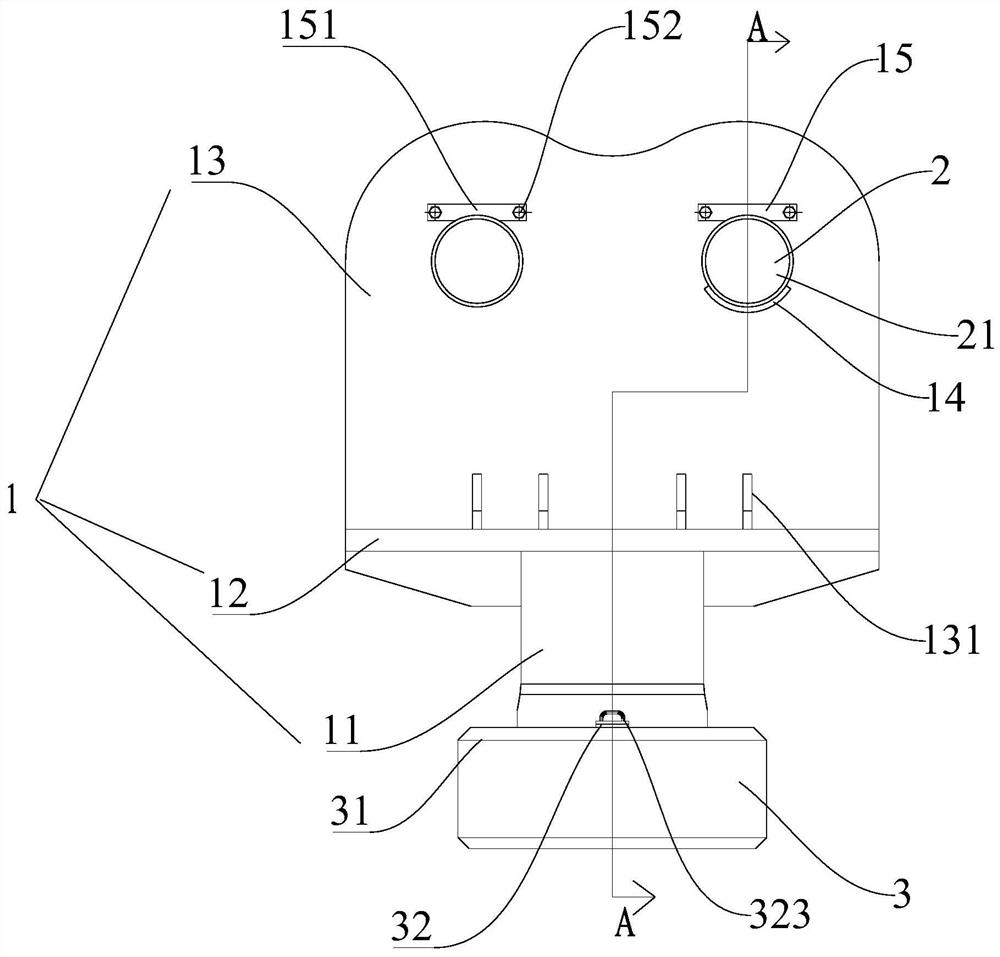
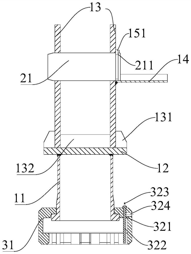
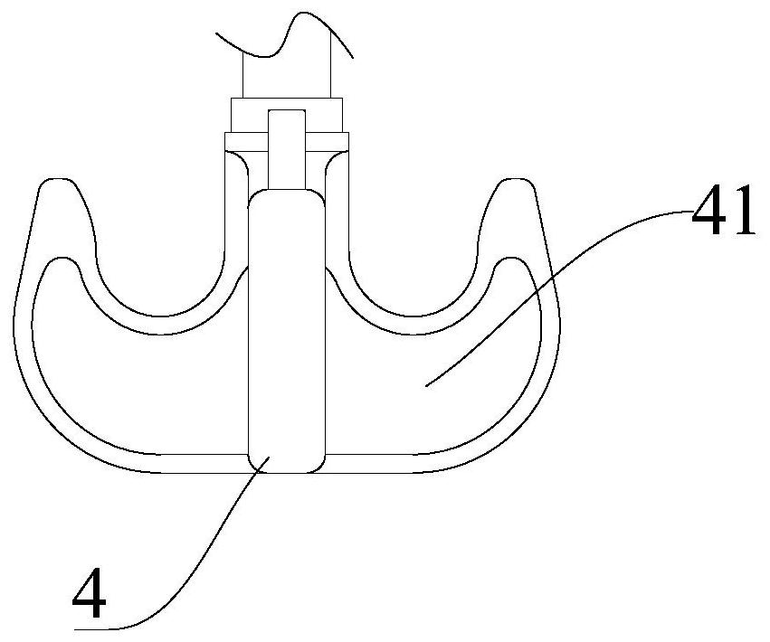
[0043] Such as Figure 1-10 As shown, a lifting device for a heavy-duty drilling tool in this embodiment is specially used for lifting a drilling tool of a large shaft drilling rig, and includes a lifting tool main body 1 , a crane connecting part 2 and a hanging object connecting part 3 . The main body 1 of the spreader includes a cylinder body 11, a horizontal plate 12 is connected to the upper end of the cylinder body 11, and two vertical plates 13 opposite to each other are installed on the horizontal plate 12. The crane connector 2 includes two pin shafts 21; the two pin shafts 21 are inserted horizontally between the two vertical plates 13, and are articulated and matched with the hook head 4 of the gantry crane. The hanging object connector 3 includes a hanging pan 31; the hanging pan 31 is installed at the lower end of the cylinder body 11, and the opening 311 of the hanging pan 31 is downward; the opening 311 is clamped and fitted with the upper interface 5 of the dri...


PUM


Abstract

The invention relates to the technical field of drilling tool hoisting, and provides a hoisting device for a heavy drilling tool. The hoisting device comprises a hoisting tool main body, a crane connecting piece and a hoisting object connecting piece. The hoisting tool main body comprises a barrel. The upper end of the barrel is connected with a horizontal plate. Two opposite vertical plates are arranged on the horizontal plate. The crane connecting piece comprises two pin shafts. The two pin shafts are horizontally inserted between the two vertical plates and are in hanging fit with a door type crane hook head. The hoisting object connecting piece comprises a hoisting disc. The hoisting disc is arranged at the lower end of the barrel, and an opening of the hoisting disc is downward. The opening is in clamping fit with a connector on the drilling tool. The hoisting device has the beneficial effects that the hoisting device is simple and convenient to operate, various problems caused by adoption of a traditional steel wire rope can be effectively avoided, the construction work requirement is met, the hoisting safety is improved, the work time is saved, and meanwhile the work labor intensity is reduced.

Description

technical field [0001] The invention relates to the technical field of drilling tool hoisting, in particular to a lifting device for heavy drilling tools. Background technique [0002] With the rapid development of my country's manufacturing technology, the lifting capacity of large shaft drilling rigs and gantry cranes in mines has been greatly improved, and the weight of drilling tools has also increased. [0003] The weight of the current drilling tool assembly can reach 400T, and the drilling tool needs to be brought up to the ground for maintenance after a certain period of use. This creates a problem: whether to adopt the method of dismantling the drilling tool and lifting it piece by piece, or lifting and repairing the drilling tool as a whole. If the drilling tool is disassembled and then hoisted and overhauled one by one, it will take a long time, which will greatly affect the operating efficiency. The overall lifting and maintenance method of drilling tools can sa...

Claims


Application Information

Patent Timeline
Patent Type & Authority Applications(China)
IPC IPC(8): B66C1/10
CPCB66C1/10
Inventor 赵伟峰杨光王宗金晏中俊李新利冯金亮刘峰刘伟军李奕魏奎赵明河田月祥郭厚才周立亮
Owner CHINA COAL SPECIAL DRILLING ENG
Why Eureka
Eureka Blog
Learn More