Underground pipeline detection robot and detection method thereof
A technology for underground pipelines and robots, applied in special pipes, pipe components, mechanical equipment, etc., can solve the problem of being unable to bypass obstacles by itself, and achieve the effect of reducing the risk of rollover and improving detection stability.
- Summary
- Abstract
- Description
- Claims
- Application Information
AI Technical Summary
Problems solved by technology
Method used
Image
Examples
Embodiment 1
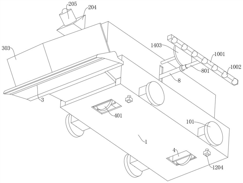
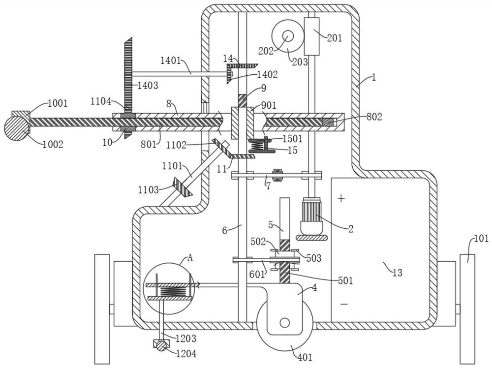
[0035] refer to Figure 1-10, an underground pipeline detection robot, including a housing 1 and a probe 205, the probe 205 is connected to the front end of the housing 1, and also includes: a side plate 303, connected to the front end of the housing 1, the front end is one end of the robot’s forward direction, and the side plate 303 Inclined to both sides of the housing 1, the side plate 303 is V-shaped, and the two sides are inclined to both sides of the housing 1; the lifting frame 4 is two symmetrically designed, and the two lifting frames 4 are slidingly connected in the housing 1 , a connecting plate 403 is fixedly connected between the two lifting frames 4; a moving wheel 401 that drives the housing 1 to move laterally, the moving wheel 401 is rotatably connected in the lifting frame 4, and a motor 402 is fixedly connected to the side wall of the lifting frame 4, and the motor 402 The output end is connected with the moving wheel 401; the housing 1 is provided with a dr...
Embodiment 2
[0040] refer to Figure 1-10 , on the basis of Example 1, further,
[0041] This embodiment discloses a driving mechanism. The driving mechanism includes a motor 2 and a second rotating shaft 6. The motor 2 is fixedly connected in the casing 1, and the second rotating shaft 6 is rotatably connected in the casing 1. The output end of the motor 2 is connected to the second rotating shaft. The two rotating shafts 6 are connected by the second belt 7, the top of the lifting frame 4 is fixedly connected with the fixed shaft 5, the fixed shaft 5 is provided with a first threaded rod 501, and the first threaded rod 501 is threaded with a first threaded sleeve 502 , the first threaded sleeve 502 is connected to the second rotating shaft 6 through the first belt 601 , the inside of the housing 1 is fixedly connected with the limiting plate 503 , and the limiting plate 503 is attached to the upper and lower ends of the first threaded sleeve 502 .
[0042] Start the motor 2, the motor 2...
Embodiment 3
[0046] refer to Figure 1-10 , on the basis of Example 2, further,
[0047] The second rotating shaft 6 is provided with a third threaded rod 9, and the third threaded rod 9 is threadedly connected with a second threaded sleeve 901, and the hollow cylinder 8 extends to a sliding sleeve 902 on the side surface of the housing 1, and the second threaded sleeve 902 is The sleeve 901 and the sliding sleeve 902 are rotationally connected, the hollow cylinder 8 is slidingly connected with a second threaded rod 801, and one end of the second threaded rod 801 extending out of the hollow cylinder 8 is fixedly connected with a support plate 1001, and the first rolling ball 1002 is connected to the On the support plate 1001, the side wall of the housing 1 is provided with a control mechanism that drives the second threaded rod 801 to slide on the hollow cylinder 8 when one end of the hollow cylinder 8 extending out of the housing 1 is rotated to the lowest end, and the second belt 7 is lo...
PUM
 Abstract
Description
Claims
Application Information
 - R&D
- Intellectual Property
- Life Sciences
- Materials
- Tech Scout
- Unparalleled Data Quality
- Higher Quality Content
- 60% Fewer Hallucinations
Browse by: Latest US Patents, China's latest patents, Technical Efficacy Thesaurus, Application Domain, Technology Topic, Popular Technical Reports.
© 2025 PatSnap. All rights reserved.Legal|Privacy policy|Modern Slavery Act Transparency Statement|Sitemap|About US| Contact US: help@patsnap.com


