Fluorescent optical fiber temperature measurement system based on wireless sensing and method thereof

A fluorescent optical fiber and wireless sensing technology, applied in the field of fluorescent optical fiber temperature measurement system, can solve the problem of inaccurate measurement

Active Publication Date: 2022-01-21
中国电建集团海南电力设计研究院有限公司
View PDF11 Cites 0 Cited by
  • Summary
  • Abstract
  • Description
  • Claims
  • Application Information

AI Technical Summary

Problems solved by technology

[0004] At present, the conventional method is to simulate or calculate the temperature value, but it cannot be accurately measured. Therefore, it is urgent to provide a system or method that can measure the actual temperature value of the winding to solve this problem

Method used


Image

  • Fluorescent optical fiber temperature measurement system based on wireless sensing and method thereof
  • Fluorescent optical fiber temperature measurement system based on wireless sensing and method thereof
  • Fluorescent optical fiber temperature measurement system based on wireless sensing and method thereof

Examples


Embodiment 1

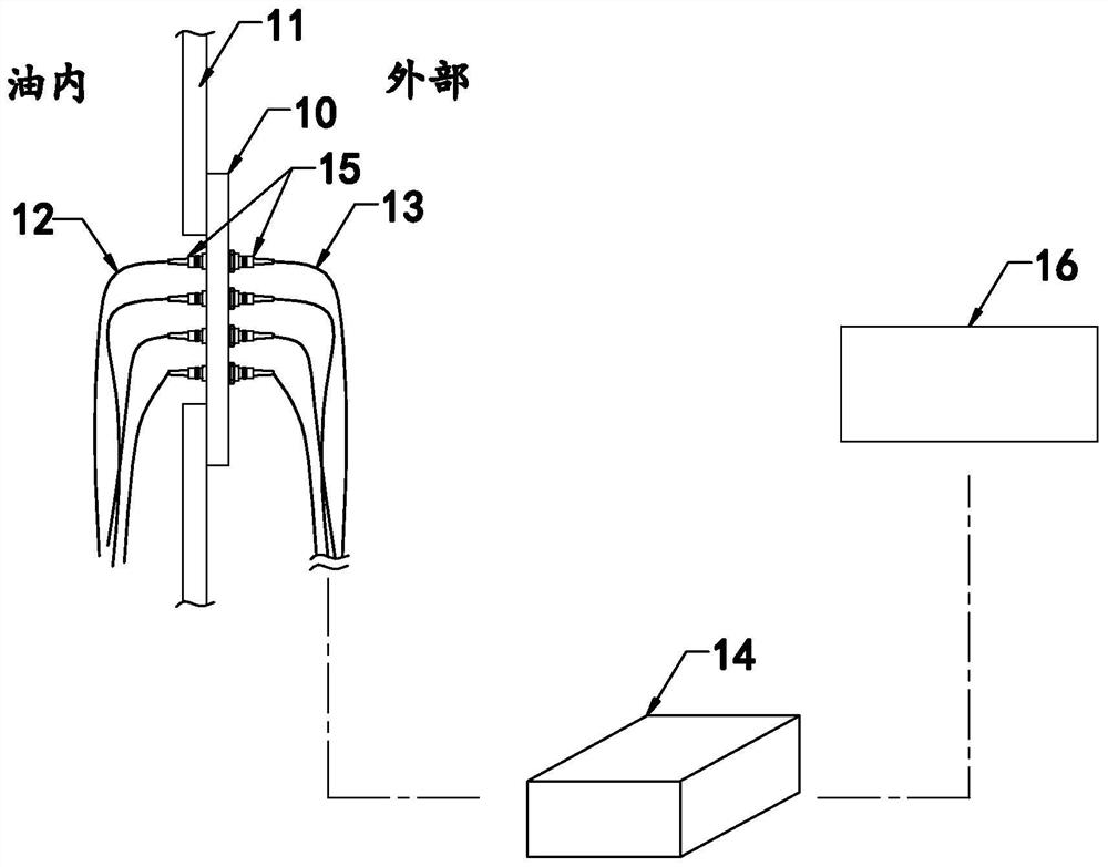
[0092] Such as figure 1 As shown, the invention discloses a fluorescent optical fiber temperature measurement system based on wireless sensing, characterized in that: comprising:

[0093] The through disk 10 is installed on the wall 11 of the transformer oil tank and has several optical fiber interfaces;

[0094] The oil-resistant optical fiber 12 is located in the transformer oil tank, and one end extends to the optical fiber interface, and the other end extends to the transformer winding, and an optical fiber probe is provided at this end;

[0095] An optical fiber jumper 13 is located outside the transformer, and one end extends to the optical fiber interface, and the other end is connected to an optical fiber temperature controller 14;

[0096] The through device 15 is arranged at each optical fiber interface, and is used to connect the oil-resistant optical fiber 12 and the optical fiber jumper 13;

[0097] The serial server 16 is connected with the optical fiber temper...

Embodiment 2

[0101] Embodiment 2, the difference with embodiment 1 is:

[0102] Such as Figure 2-Figure 9 Shown:

[0103] In a specific embodiment of the invention, it also includes:

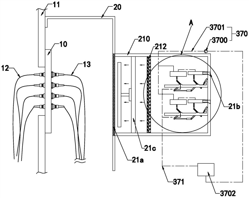
[0104] The protective cover 20 is installed on the wall 11 of the transformer oil tank, and can cover and accommodate the through disk 10, the optical fiber jumper 13 and the optical fiber temperature controller 14;

[0105] The cooling device 21 is arranged on any side of the protective cover 20, and has at least an air inlet end, an air outlet end, and an air source 21c. When the air source 21c is activated, it can generate an airflow flowing from the air inlet end to the air outlet end;

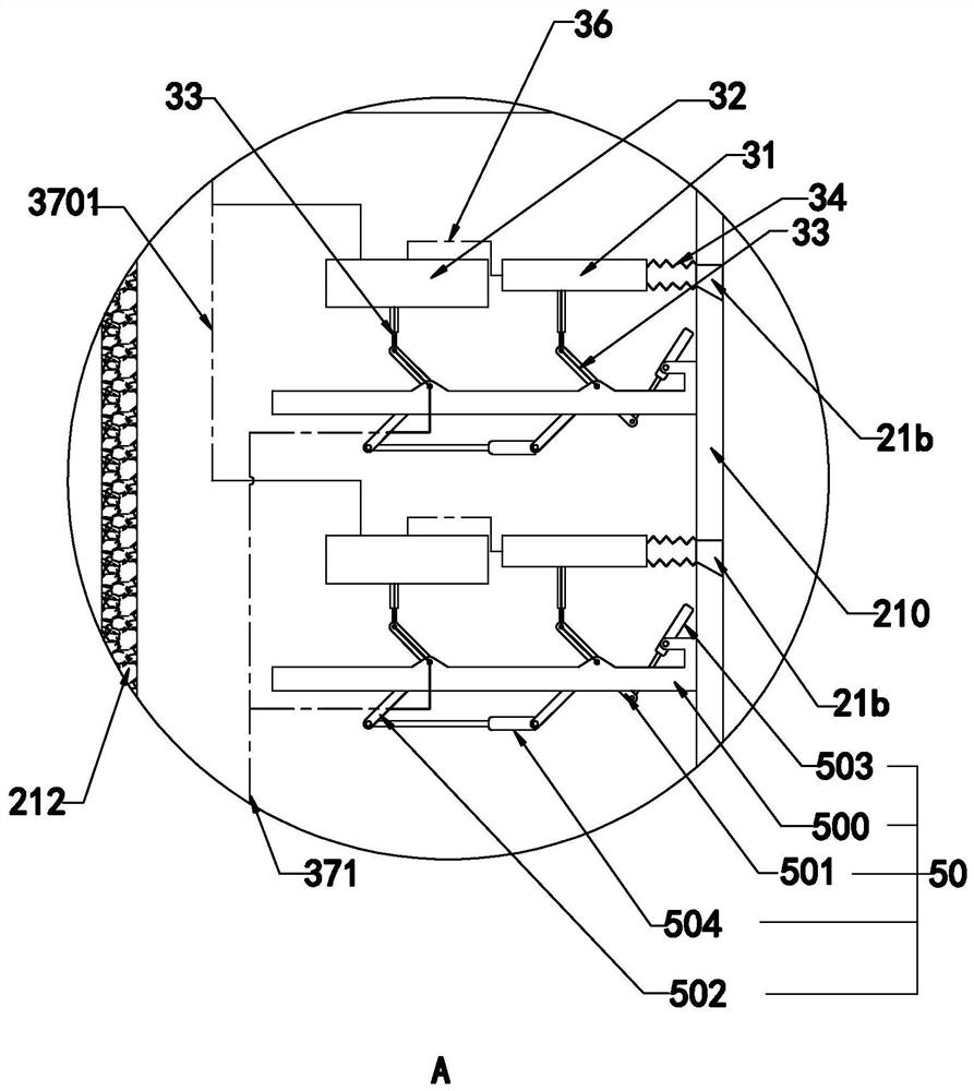
[0106] Wherein, the cooling device 21 has at least a housing 210, a refrigeration unit 211 and a dehumidification unit 212. The air inlet end is arranged on the housing 210. When the air source 21c is activated, the airflow passes through the refrigeration unit 211 and the dehumidification unit 212 and into the prote...


PUM


Abstract

The invention relates to a fluorescent optical fiber temperature measurement system based on wireless sensing and a method thereof, and the system is characterized in that the system comprises: a cut-through disc which is disposed on the wall of a transformer oil tank, and is provided with a plurality of optical fiber interfaces; an oil-resistant optical fiber which is located in the transformer oil tank, wherein one end of the oil-resistant optical fiber extends to the optical fiber interface, and the other end of the oil-resistant optical fiber extends to the transformer winding and is provided with an optical fiber probe; an optical fiber patch cord, wherein the optical fiber patch cord is located outside the transformer, one end of the optical fiber patch cord extends to the optical fiber interface, and the other end of the optical fiber patch cord is connected with an optical fiber temperature controller; cut-through devices are arranged at the optical fiber interfaces and are used for connecting the oil-resistant optical fiber and the optical fiber patch cord; and a serial server which is connected with the optical fiber temperature controller and is wirelessly connected with a background computer. The actual temperature of the transformer winding can be detected.

Description

technical field [0001] The invention relates to the technical field of transformer winding temperature measurement, in particular to a fluorescent optical fiber temperature measurement system and method based on wireless sensing. Background technique [0002] Transformer refers to a device that uses the principle of electromagnetic induction to change AC voltage. Its main components are primary coil, secondary coil and iron core (or magnetic core). [0003] During the use of transformers, when an overload occurs, the transformer will usually bear the brunt. Therefore, it is very important to monitor the thermal power of the transformer windings, which can protect the transformer from damage or even excessive use. [0004] At present, the conventional method is to simulate or calculate the temperature value, but it cannot be accurately measured. Therefore, it is urgent to provide a system or method capable of measuring the actual temperature value of the winding to solve this...

Claims


Application Information

Patent Timeline
IPC IPC(8): G01K11/32G01K1/024
CPCG01K11/32G01K1/024
Inventor 成美丽蔡儒军焦国锋吴俊鹏陈步福朱明伟黄赞频张盛
Owner 中国电建集团海南电力设计研究院有限公司
Why Eureka
Try Eureka