
High-frequency thermal stimulator and thermal stimulation method using same

A stimulator and warming technology, applied in phototherapy, electrotherapy, radiation therapy, etc., can solve problems such as easy accumulation of fatigue, unstable pressure, discomfort and fear, and achieve the discomfort or fear of sparks and the possibility of burns The effect of minimizing sex, reducing operation time, and improving therapeutic effect

Pending Publication Date: 2022-01-25
HUREV CO LTD
View PDF0 Cites 0 Cited by
  • Summary
  • Abstract
  • Description
  • Claims
  • Application Information

AI Technical Summary

Problems solved by technology

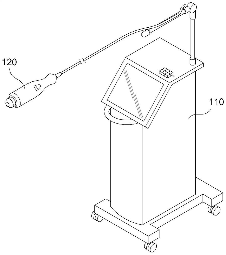
[0003] However, in the case of this existing high-frequency thermal stimulator, a high-frequency current with a fixed negative polarity is applied to each electrode of the hand piece 120, so the area where deep heat is generated is narrow, resulting in a heat generation inside the body. decreased, so there is a problem that the treatment effect is minimal
[0004] In addition, as described above, the polarity of the high-frequency current applied to each electrode is fixed. Therefore, when the surgical site is wide, the high-frequency current is applied while continuously moving the electrodes in contact with the skin. Therefore, fatigue is easily accumulated on the hand operating the hand piece, and the pressure applied by the electrodes to the skin is unstable, so that sparks may be generated due to unstable contact between the electrodes and the skin. Sparks, not only the treated person will feel severe discomfort and fear, but in severe cases there is a problem of skin burns

Method used


Image

  • High-frequency thermal stimulator and thermal stimulation method using same
  • High-frequency thermal stimulator and thermal stimulation method using same
  • High-frequency thermal stimulator and thermal stimulation method using same

Examples


Embodiment Construction

[0037] Preferred embodiments according to the present invention will be described in detail below with reference to the accompanying drawings. Before proceeding with the description, it should be reminded that the terms or words used in this specification and claims should not be limited to the usual or dictionary meanings, and should be based on the best way for the inventor to explain them. The principle of being able to precisely define the concept of terminology based on my own invention is interpreted as a meaning and concept consistent with the technical thought of the present invention.

[0038] Therefore, the embodiments described in this specification and the configuration shown in the accompanying drawings are only the best embodiment of the present invention, and do not represent all technical ideas of the present invention. Therefore, on the occasion of this application, it should be understood that There are various equivalents and modifications that can be substi...


PUM


Abstract

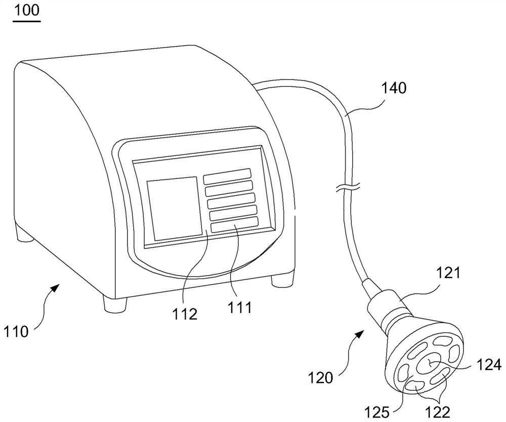
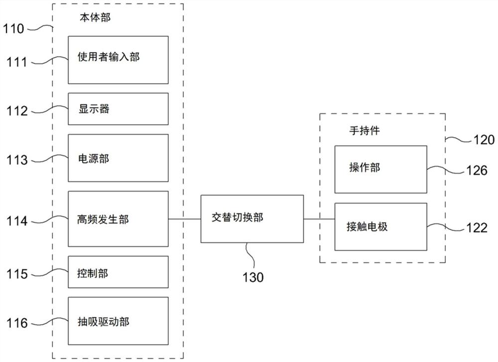
According to the present invention, disclosed is a high-frequency thermal stimulator. The thermal stimulator comprises a main body comprising a high-frequency generation unit for generating a high-frequency current by means of a supplied drive power source; a handheld piece, which is connected to the main body by means of a cable, is provided with a handle to be held by a user at the upper part of the handheld piece, and has four or more contact electrodes disposed at a distance from each other on the lower surface of the handheld piece, wherein the contact electrodes generates deep heat inside the body by applying a supplied high-frequency current to the skin that is in contact with the handheld piece; and an alternating switching unit, which is electrically connected between the high-frequency generation unit and each of the contact electrodes, supplies the high-frequency current output from the high-frequency generation unit to the contact electrodes, divides the contact electrodes in such a manner that each two contact electrodes form a pair, and alternately supplies the high-frequency current to each pair of contact electrodes at a first speed.

Description

technical field [0001] The present invention relates to a high-frequency thermostimulator and a thermostimulation method using it (HIGH FREQUENCY HYPERTHERMIA DEVICE AND HYPERTHERMIA METHOD USING THE SAME), and more specifically, relates to a method for applying high-frequency energy to the skin to stimulate the inside of the body or It is a high-frequency thermostimulator and a thermostimulation method using it that generates deep heat around the skin to induce improvement of skin tissue, melting of visceral fat, necrosis of cancer cells, and other body treatments. Background technique [0002] figure 1 The diagram in the middle has the composition of the existing high-frequency thermotherapy instrument. With reference to the accompanying drawings, the existing high-frequency thermal stimulator is generally composed of a body 110 and a handpiece 120. The body 110 is powered by an external power source to generate a high-frequency current, and the high-frequency current is ...

Claims


Application Information

Patent Timeline
Patent Type & Authority Applications(China)
IPC IPC(8): A61N1/40A61N1/04A61N1/02
CPCA61N1/403A61N1/0476A61N1/02A61N1/06A61N1/36A61B2018/124A61B2018/00464A61B2018/1467A61B2018/126A61N1/328A61N1/36002A61N5/0616A61N5/0624A61N2005/0644A61N2005/0651A61B18/1206A61B18/14A61B18/1402A61B2018/0016A61B2018/00208A61B2018/00291A61B2018/00458A61B2018/0066A61B2018/0072A61B2018/00732A61B2018/00738A61B2018/00922A61B2018/00994A61N1/08A61N5/06A61N2005/0652A61N5/067A61N2005/0649A61B2018/0047
Inventor 柳基弘
Owner HUREV CO LTD
Learn More