Automatic coupling method and system for head coupler buffer device of urban rail vehicle

A technology for urban rail vehicles and continuous suspension, which is applied in the directions of railway vehicle coupling parts, transportation and packaging, and railway car body parts, etc.

Active Publication Date: 2022-01-25
QINGDAO SRI TECH CO LTD
View PDF8 Cites 3 Cited by
  • Summary
  • Abstract
  • Description
  • Claims
  • Application Information

AI Technical Summary

Problems solved by technology

[0004] In recent years, due to the use of unmanned (autonomous driving) vehicles, straddling monorail vehicles and the increase in elevated lines, occasionally there are no rescuers on site (unmanned driving) or rescuers cannot operate smoothly (straddling monorail, some elevated lines) line, third rail live operation safety issues) phenomenon
When the accident train of the above-mentioned vehicles or lines stops on a small curve, it will not be possible to realize the timely rescue of the train, which will seriously affect the transportation capacity of the line
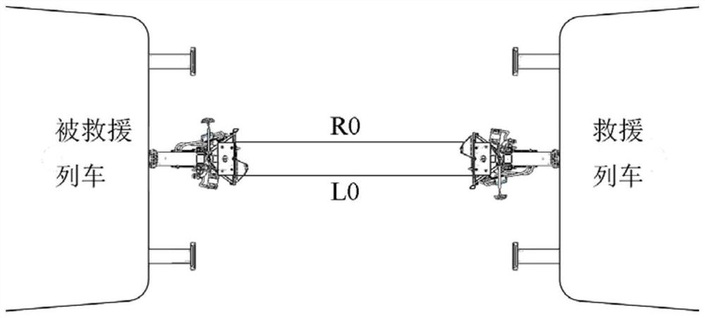
[0005] In order to realize the full-range automatic connection function of rail vehicles, some personnel set up the automatic swing function on the head hook, but it is impossible to determine the automatic connection position of the head hook of the rescue train according to the actual route situation. When the automatic connection position is not set properly, it may cause security incident

Method used


Image

  • Automatic coupling method and system for head coupler buffer device of urban rail vehicle
  • Automatic coupling method and system for head coupler buffer device of urban rail vehicle
  • Automatic coupling method and system for head coupler buffer device of urban rail vehicle

Examples


Embodiment Construction

[0046]The technical solutions of the present application will be described in detail below in conjunction with specific embodiments. However, it should be understood that without further description, elements, structures and features in one embodiment can also be beneficially combined in other embodiments.

[0047] It is to be understood that, although the figures may show a specific order of method steps, the order of steps may vary from that depicted. Furthermore, two or more steps may be performed concurrently or with partial concurrence. Such variations will depend on the software and hardware selected, as well as designer choice. All such variations are within the scope of this disclosure.

[0048] It should be understood that the term "system", "unit" and "module" used herein is a method used to distinguish different components, elements, parts, parts or assemblies at different levels. However, these terms may be replaced by other expressions that serve the same purpos...


PUM


Abstract

The invention provides an automatic coupling method and system for a head coupler buffer device of an urban rail vehicle. A coupling datum point is obtained on the basis of combination of distance measurement and an automatic swing function of a head coupler, automatic coupling of the head coupler at any position on a line can be achieved on the basis of the coupling datum point, the waiting time of personnel is shortened, and the safety of the personnel is guaranteed. According to the automatic coupling method, position detection of the head coupler can be automatically completed, the deflection direction of the head coupler for realizing automatic coupling is judged, and the automatic coupling of the head coupler is finally realized on the basis of the automatic swinging function of the head coupler.

Description

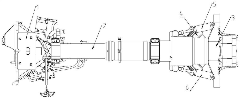
technical field [0001] The application belongs to the technical field of coupler buffer devices, and in particular relates to an automatic coupling method and system for a coupler buffer device of an urban rail vehicle. Background technique [0002] The coupler buffer device is an important component of the urban rail vehicle. It is arranged at both ends of the urban rail vehicle. According to its location, it can be divided into two categories: the head coupler buffer device (hereinafter referred to as "head coupler") and the middle coupler buffer device. Among them, the main function of the middle coupler buffer device is to realize the mechanical and air connection between the vehicles, and to form a complete train with multiple vehicles; the main function of the head coupler buffer device is to connect the trains mechanically and electrically to achieve reconnection. The purpose of operation is to improve the carrying capacity of trains or to complete the rescue of broke...

Claims


Application Information

Patent Timeline
Patent Type & Authority Applications(China)
IPC IPC(8): B61G7/00B61G7/06
CPCB61G7/00B61G7/06
Inventor 王冬春刘旭东尚琦琦田倩倩刘辉王晓鹏高鹏王博
Owner QINGDAO SRI TECH CO LTD
Why Eureka
Try Eureka