Supercharge Your Innovation With Domain-Expert AI Agents!

Underground pipeline leakage point detection device and detection method thereof

A detection device and a technology for underground pipelines, which are applied to measurement devices, mechanical measurement devices, and mechanical devices, etc., can solve the problems of inconvenient pipeline blockage, time-consuming and labor-intensive, complicated operation, etc., and achieve accurate and reliable detection results. The effect of work efficiency and high safety

Pending Publication Date: 2022-01-25
上海派普诺管道检测科技发展有限公司
View PDF0 Cites 1 Cited by
  • Summary
  • Abstract
  • Description
  • Claims
  • Application Information

AI Technical Summary

Problems solved by technology

As people's requirements for the environment become higher and higher, and the technology of direct burial of pipelines continues to mature, more and more pipelines are directly buried underground. When there is leakage in the pipeline, it is first necessary to determine the point of infiltration or leakage. Overhead pipe leaks that were easy to find are now very difficult
[0003] In related technologies, when detecting leaks in underground pipelines, it is generally necessary to manually use a pipeline detector to detect the pipeline segment by segment, so as to find the leaks of the pipeline. Before the detection process, both ends of the pipeline need to be blocked. When plugging, rubber plugs or other plugging devices are often used to seal both ends of the pipeline manually. The cost of plugging is relatively high, and the operation is complicated, which consumes a lot of time and manpower.
[0004] In view of the related technologies mentioned above, the inventor believes that it is inconvenient to block the pipeline when detecting pipeline leaks in the related technology, which leads to the problem of low detection efficiency of pipeline leaks

Method used


Image

  • Underground pipeline leakage point detection device and detection method thereof
  • Underground pipeline leakage point detection device and detection method thereof
  • Underground pipeline leakage point detection device and detection method thereof

Examples


Embodiment Construction

[0039] The following is attached Figure 1-4 The application is described in further detail.

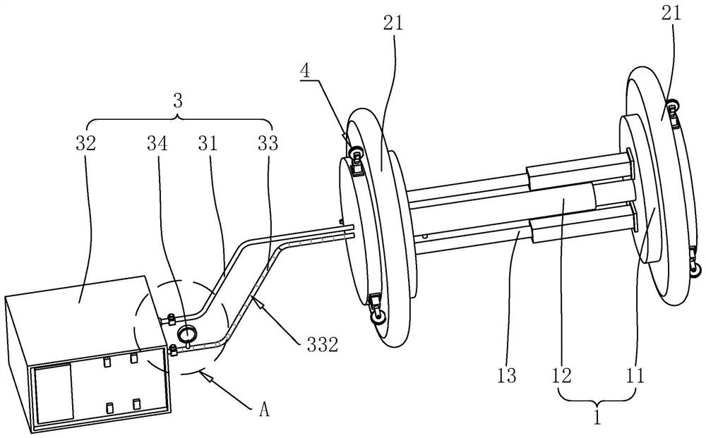
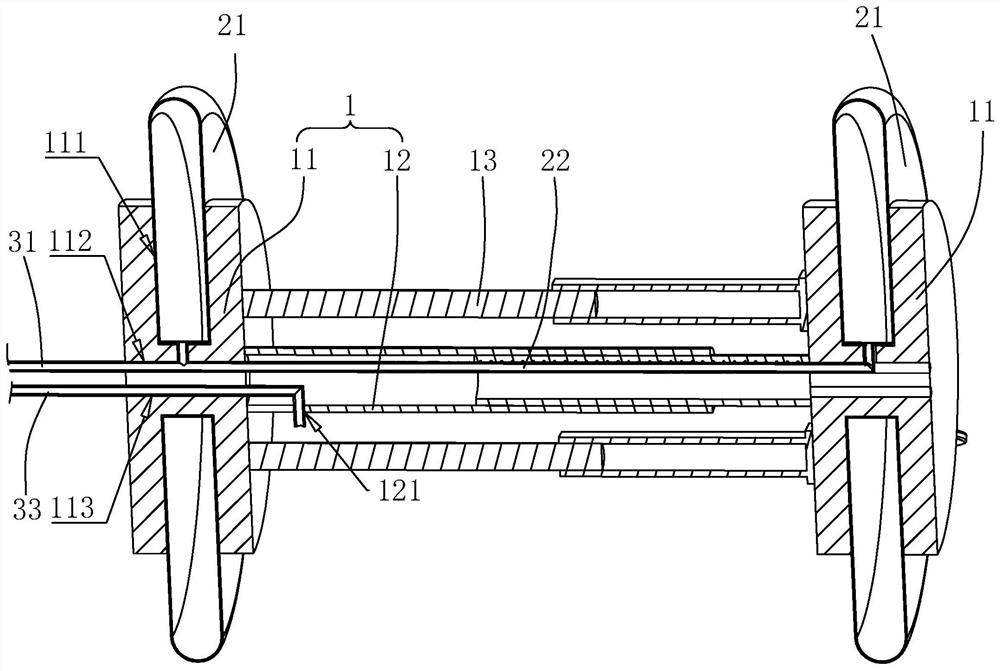
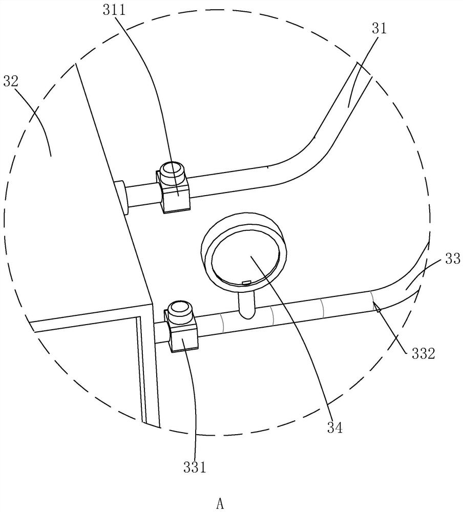
[0040] The embodiment of the present application discloses an underground pipeline leakage detection device. refer to figure 1 with figure 2 , an underground pipeline leak detection device includes a frame body 1 , a plugging assembly 2 , a detection assembly 3 and a walking assembly 4 .

[0041] refer to figure 1 with figure 2 , the frame body 1 includes two mounting plates 11 and a connecting rod 12, the connecting rod 12 is a telescopic rod, the connecting rod 12 is a secondary telescopic rod in this embodiment, and the two mounting plates 11 are respectively located at the ends of the connecting rod 12 along the length direction. At both ends, the mounting plate 11 is coaxially welded with the connecting rod 12, and the frame body 1 is provided with two first cylinders 13, the cylinder body of the first cylinder 13 and any mounting plate 11 are fixedly connected by screws,...


PUM


Abstract

The invention relates to an underground pipeline leakage point detection device and a detection method thereof. The underground pipeline leakage point detection device comprises a frame body, a plugging assembly and a detection assembly, the plugging assembly comprises a connecting pipe and two air bags, the two air bags are located at the two ends, in the axial direction of a pipeline, of the frame body correspondingly, the two air bags are fixedly communicated through the connecting pipe and the detection assembly communicates with any air bag and is used for inflating the air bags. The underground pipeline leakage point detection method comprises the following steps: S1, putting a detection device into a pipeline; S2, inflating the air bag until the air bag seals the pipeline; S3, inflating the sealing section, and then judging whether a leakage point exists in the pipe section or not according to the reading change of the pressure gauge; and S4, moving the detection device along the axial direction of the pipeline, and repeating the steps S2 and S3 until the whole section of the pipeline is detected. The device and the method have the effect of improving the detection efficiency when the pipeline leakage point is detected.

Description

technical field [0001] The present application relates to the technical field of pipeline detection, in particular to an underground pipeline leak detection device and a detection method thereof. Background technique [0002] Pipelines are drainage and air supply facilities that are often used in municipal engineering. As people's requirements for the environment become higher and higher, and the technology of direct burial of pipelines continues to mature, more and more pipelines are directly buried underground. When there is leakage in the pipeline, it is first necessary to determine the point of infiltration or leakage. Leaks in overhead pipes that were easy to find are now very difficult. [0003] In related technologies, when detecting leaks in underground pipelines, it is generally necessary to manually use a pipeline detector to detect the pipeline segment by segment, so as to find the leaks of the pipeline. Before the detection process, both ends of the pipeline nee...

Claims


Application Information

Patent Timeline
IPC IPC(8): G01M3/28G01B5/02
CPCG01M3/2815G01B5/02
Inventor 石青刘兆成王世波
Owner 上海派普诺管道检测科技发展有限公司
Features
  • R&D
  • Intellectual Property
  • Life Sciences
  • Materials
  • Tech Scout
  • Unparalleled Data Quality
  • Higher Quality Content
  • 60% Fewer Hallucinations
Learn More