
Stator, motor, fluid pump and vehicle

A stator and stator yoke technology, which is applied in the field of vehicles, can solve the problems that the current cannot be increased without limit, the air gap of the permanent magnet motor is large, and the wiring overlaps and crosses, etc., and achieve the effects of simple structure, improved motor performance, and reliable connection

Active Publication Date: 2022-01-25
ANHUI WELLING AUTO PARTS CO LTD +1
View PDF14 Cites 1 Cited by
  • Summary
  • Abstract
  • Description
  • Claims
  • Application Information

AI Technical Summary

Problems solved by technology

[0002] For fluid pumps used in vehicles, such as electronic water pumps or electronic oil pumps, the permanent magnet motor has a large air gap, and the effective permanent magnet magnetic field is weak. In order to achieve the head and efficiency required by the electronic water pump, the current cannot be increased without limit, and at the same time, the motor generates heat. limit, can only increase the number of coil turns
Due to the large number of turns of the coil, when the winding machine is winding, it is easy to make the wiring overlap and cross, resulting in a short circuit between turns

Method used


Image

  • Stator, motor, fluid pump and vehicle
  • Stator, motor, fluid pump and vehicle
  • Stator, motor, fluid pump and vehicle

Examples


Embodiment Construction

[0048] Embodiments of the invention are described in detail below, examples of which are illustrated in the accompanying drawings. The embodiments described below by referring to the figures are exemplary and are intended to explain the present invention and should not be construed as limiting the present invention.

[0049] In describing the present invention, it should be understood that the terms "center", "longitudinal", "transverse", "length", "width", "thickness", "upper", "lower", "front", " Back", "Left", "Right", "Vertical", "Horizontal", "Top", "Bottom", "Inner", "Outer", "Clockwise", "Counterclockwise", "Axial", The orientation or positional relationship indicated by "radial", "circumferential", etc. is based on the orientation or positional relationship shown in the drawings, and is only for the convenience of describing the present invention and simplifying the description, rather than indicating or implying the referred device or element Must be in a particular ...


PUM


Abstract

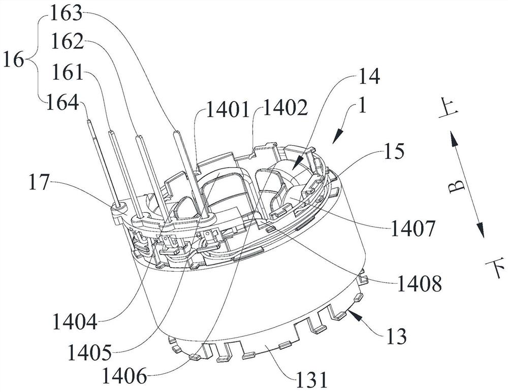
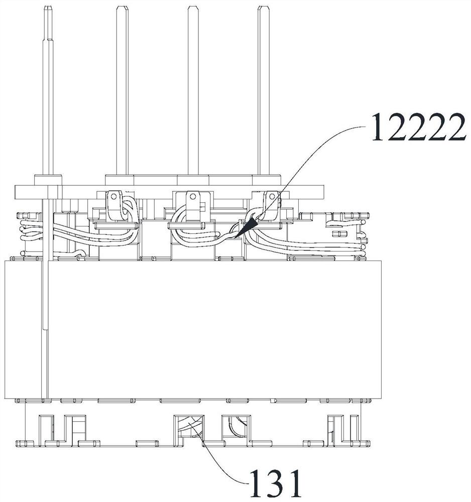
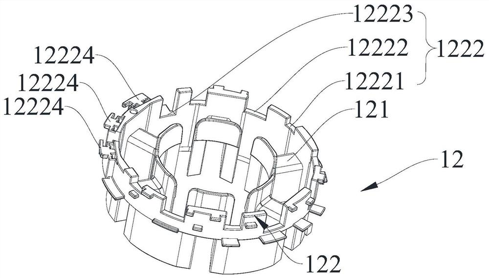
The invention provides a stator, a motor with the stator, a fluid pump with the motor and a vehicle comprising the fluid pump. The stator comprises a stator iron core, an upper insulating frame, a lower insulating frame and a plurality of wiring terminals; the upper insulating frame comprises an upper inserting part and an upper extending part, and the lower insulating frame comprises a lower inserting part and a lower extending part. A plurality of terminal clamping grooves are formed in the peripheral wall of the upper extending part, a plurality of notches extending downwards by different depths are formed in the upper end face of the upper extending part, a plurality of protrusions are arranged on the peripheral wall of the upper extending part and arranged into multiple layers spaced in the axial direction of the upper insulating frame, and wiring spaces are formed between the adjacent layers. The protrusions on the same layer are distributed at intervals in the circumferential direction of the upper insulating frame, connecting lines of the multiple windings are led out of the notches and distributed in the wiring space in the circumferential direction of the upper insulating frame, and the wiring terminals are inserted into the multiple terminal clamping grooves respectively. According to the stator provided by the invention, the wiring terminals are convenient to install, the windings are prevented from overlapping and crossing, and the motor performance is improved.

Description

technical field [0001] The present invention relates to the technical field of motors, in particular to a stator, a motor with the stator, a fluid pump with the motor and a vehicle including the fluid pump. Background technique [0002] For fluid pumps used in vehicles, such as electronic water pumps or electronic oil pumps, the permanent magnet motor has a large air gap, and the effective permanent magnet magnetic field is weak. In order to achieve the head and efficiency required by the electronic water pump, the current cannot be increased without limit, and at the same time, the motor generates heat. Limitation, can only increase the number of coil turns. Due to the large number of turns of the coil, it is easy to overlap and cross the wiring when the winding machine is winding, causing a short circuit between turns. Contents of the invention [0003] The present invention aims to solve one of the technical problems in the related art at least to a certain extent. ...

Claims


Application Information

Patent Timeline
Patent Type & Authority Applications(China)
IPC IPC(8): H02K1/14H02K1/16H02K3/34H02K3/28H02K3/48H02K3/50F04D13/06
CPCH02K1/146H02K1/165H02K3/345H02K3/28H02K3/48H02K3/50F04D13/06H02K2213/03F04D13/064H02K3/522Y02T10/64
Inventor 万佳龚杰葛笑
Owner ANHUI WELLING AUTO PARTS CO LTD
Learn More