

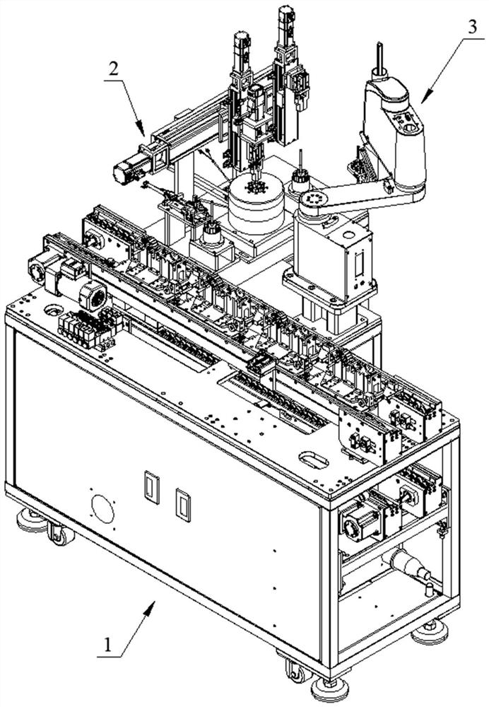
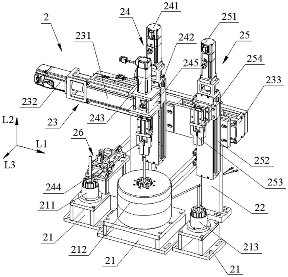
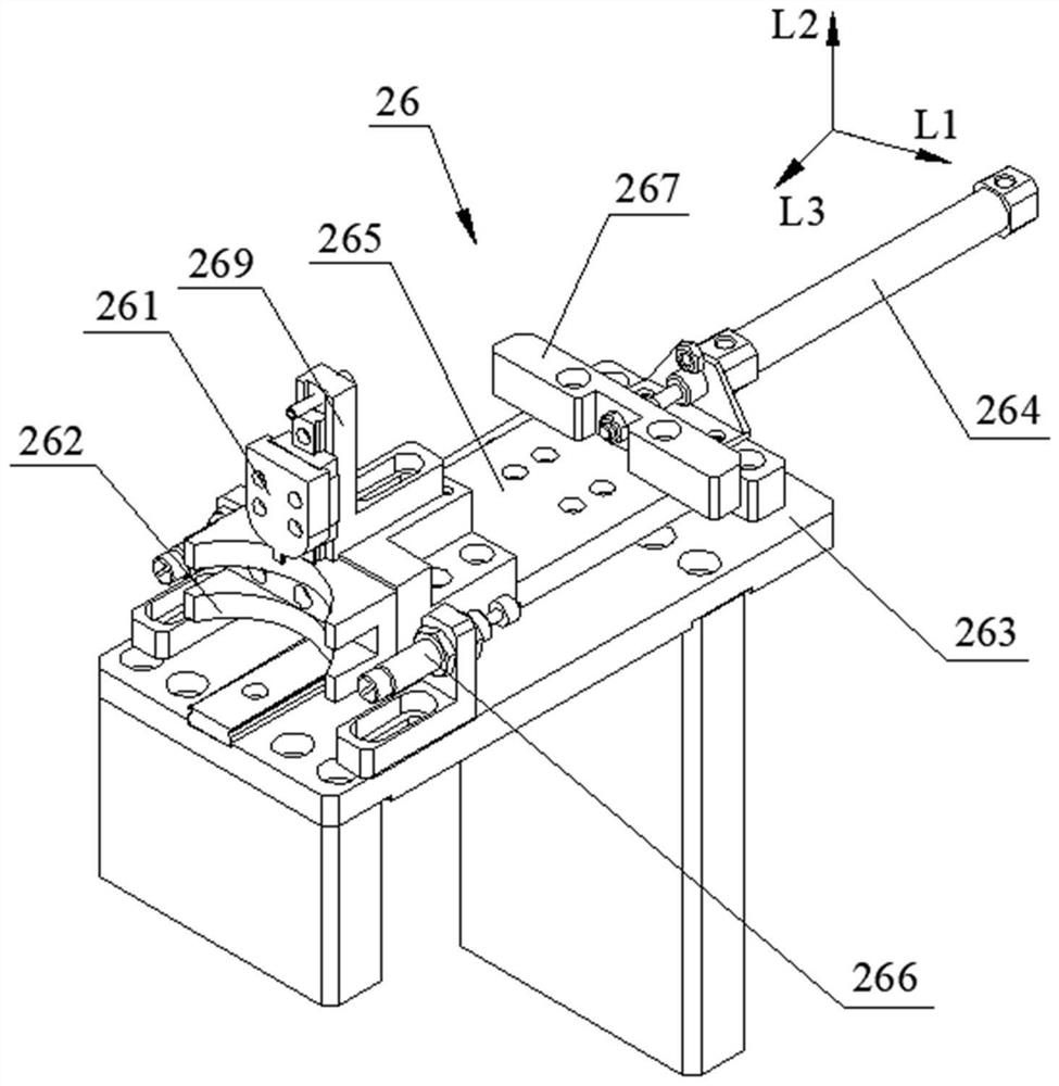
Rotor positioning device and rotor magnetizing equipment
A technology for positioning devices and magnetizing equipment, which is applied in the direction of electromechanical devices, workpiece clamping devices, manufacturing stator/rotor bodies, etc., can solve problems such as increased use costs, inconvenient operation, and complicated positioning structures, so as to save costs and speed up Batch production, the effect of improving work efficiency
- Summary
- Abstract
- Description
- Claims
- Application Information
AI Technical Summary
Problems solved by technology
Method used
Image

Examples
Embodiment Construction
[0035] In order to make the purpose, technical solutions and advantages of the embodiments of the present invention clearer, the technical solutions in the embodiments of the present invention will be clearly and completely described below in conjunction with the drawings in the embodiments of the present invention. Obviously, the described embodiments It is a part of embodiments of the present invention, but not all embodiments. Based on the embodiments of the present invention, all other embodiments obtained by those skilled in the art without creative efforts fall within the protection scope of the present invention.
[0036] The technical features involved in different embodiments of the present invention described below may be combined with each other as long as they do not constitute a conflict with each other.
[0037] Refer to the attached figure 1 To attach Figure 8 Describe the rotor positioning device and rotor magnetizing equipment of the present invention.
[...
PUM
 Abstract
Description
Claims
Application Information