Heat dissipation type power adapter

A power adapter and heat dissipation technology, which is applied in the direction of electrical components, power electronics modification, electrical equipment structural parts, etc., can solve problems such as hindering heat exchange between electronic components and airflow, affecting heat dissipation, etc., to reduce vibration, Reduce the effect of cushioning impact

Pending Publication Date: 2022-01-25
SHENZHEN TEKA TECH
View PDF0 Cites 3 Cited by
  • Summary
  • Abstract
  • Description
  • Claims
  • Application Information

AI Technical Summary

Problems solved by technology

[0003] At present, in the existing technology, the user will use the power adapter to charge the electric vehicle. There is a fan inside the power adapter to dissipate heat from the power adapter. However, during long-term use, external dust and catkins will enter the housing through the air inlet. , and then adhere to the internal electronic components, these dust and catkins will hinder the heat exchange between the electronic components and the airflow, thereby affecting the heat dissipation effect; therefore, a heat dissipation power adapter is proposed to solve the above problems

Method used


Image

  • Heat dissipation type power adapter
  • Heat dissipation type power adapter
  • Heat dissipation type power adapter

Examples


Embodiment 1

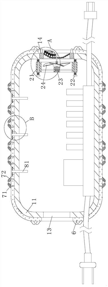
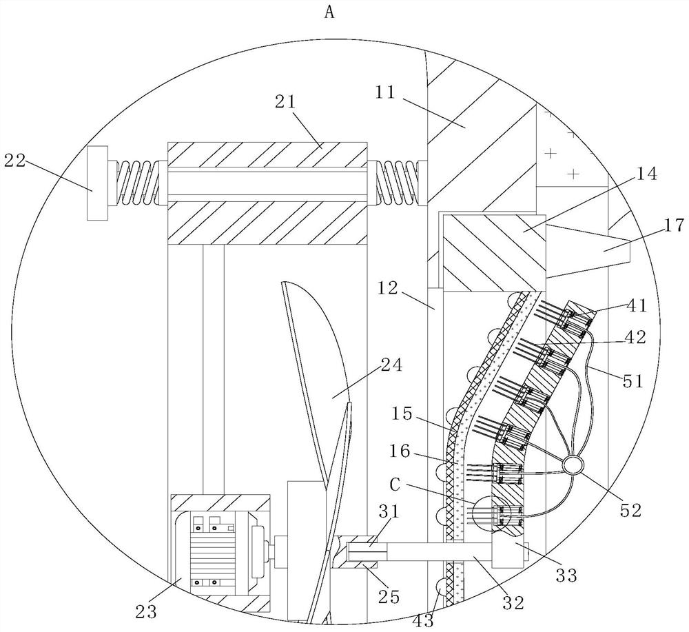
[0026] see Figure 1-5 As shown, a heat dissipation power adapter includes a housing 11, a heat dissipation unit and a fixed frame 14; an air inlet 12 is provided on one side of the housing 11, and an air outlet 13 is provided on the other side of the housing 11; The heat dissipation unit is arranged on the side wall of the housing 11; the air inlet 12 is provided with a threaded groove; the threaded groove is connected with a fixed frame 14 by threads; the fixed frame 14 is fixedly connected with a support net plate 15; The support screen 15 is fixedly connected with a filter screen 16 on the side away from the heat dissipation unit; the section of the support screen 15 is designed as a trapezoidal structure; the fixed frame 14 is provided with a block 17 on the side away from the heat dissipation unit; , by rotating the fixed frame 14, the fixed frame 14 is rotated into the thread groove to complete the installation of the filter screen 16, and by setting the clamping block ...

Embodiment 2

[0035] see Image 6 As shown in Comparative Example 1, as another embodiment of the present invention, a wax block 9 is fixedly attached to the side wall of the sliding hole; the wax block 9 is in contact with the surface of the guide rod 22. When in use, the wax block 9 will rub against the guide rod 22, and then produce some powder, through which the sliding of the guide rod 22 and the support frame 21 can be lubricated, thereby reducing the friction force and reducing the noise generated during sliding.

[0036] Working principle, during installation, by rotating the fixed frame 14, the fixed frame 14 is rotated into the threaded groove to complete the installation of the filter screen 16, and the side of the fixed frame 14 has a protrusion by setting the clamping block 17 , it is convenient to rotate the fixed frame 14, and the filter screen 16 is supported and fixed by setting the support screen 15, and the filter screen 16 is set to filter the air sucked into the housing...


PUM


Abstract

The invention belongs to the field of battery charging devices, and particularly relates to a heat dissipation type power adapter. The heat dissipation type power adapter comprises a shell, a heat dissipation unit and a fixing frame. An air inlet is formed in one side of the shell, and an air outlet is formed in the other side of the shell; the heat dissipation unit is arranged on the side wall of the shell; a threaded groove is formed in the air inlet; a fixing frame is connected into the threaded groove through threads; a supporting net plate is fixedly connected in the fixing frame; a filter screen is fixedly connected to the side, away from the heat dissipation unit, of the supporting screen plate; and the section of the supporting net plate is designed to be of a trapezoidal structure. A clamping block is arranged on the side, away from the heat dissipation unit, of the fixing frame, the fixing shell, the supporting net plate and the filter net are arranged, airflow is conducted through the filter net, dust adhering to the surfaces of internal electronic components is reduced, and then the influence of the dust and catkin on heat dissipation is reduced.

Description

technical field [0001] The invention relates to the field of battery charging devices, in particular to a heat dissipation power adapter. Background technique [0002] The power adapter refers to a device used to supply power to electronic appliances. It is mainly used to convert alternating current into direct current for output and provide power for electronic motors. [0003] At present, in the existing technology, the user will use the power adapter to charge the electric vehicle. There is a fan inside the power adapter to dissipate heat from the power adapter. However, during long-term use, external dust and catkins will enter the housing through the air inlet. , and then adhere to the internal electronic components, these dust and catkins will hinder the heat exchange between the electronic components and the airflow, thereby affecting the heat dissipation effect; therefore, a heat dissipation power adapter is proposed to solve the above problems. Contents of the inv...

Claims


Application Information

Patent Timeline
Patent Type & Authority Applications(China)
IPC IPC(8): H02M1/00H02M7/00H05K5/02H05K7/20
CPCH02M1/00H02M7/003H05K5/0213H05K7/20909H05K7/209
Inventor 钟云东肖国兴郑军
Owner SHENZHEN TEKA TECH
Why Eureka
Try Eureka