
Zoom laser processing system and method based on variable light spot diffraction element

A laser processing method and technology of diffractive elements, which are applied in the field of laser processing, can solve problems such as enlarged equipment size, unsuitable laser processing equipment, and increased length of laser processing equipment, so as to avoid lens aberration, reduce structural size, and reduce chromatic aberration Effect

Active Publication Date: 2022-01-28
FOSHAN HONGSHI LASER TECH CO LTD
View PDF18 Cites 0 Cited by
  • Summary
  • Abstract
  • Description
  • Claims
  • Application Information

AI Technical Summary

Problems solved by technology

[0002] In the field of laser processing, the existing methods of adjusting the laser focus are mostly realized by moving the lens along the axial direction, so that the focus can be dynamically changed. However, this adjustment method requires the installation of an axial displacement driver and the calculation of the axial displacement. The impact on the focus position, while driving the axial displacement of the lens will inevitably increase the length of the entire laser processing equipment in the axial direction, making the size of the equipment larger, which is not suitable for laser processing equipment with a compact structure

Method used


Image

  • Zoom laser processing system and method based on variable light spot diffraction element
  • Zoom laser processing system and method based on variable light spot diffraction element
  • Zoom laser processing system and method based on variable light spot diffraction element

Examples


Embodiment 1

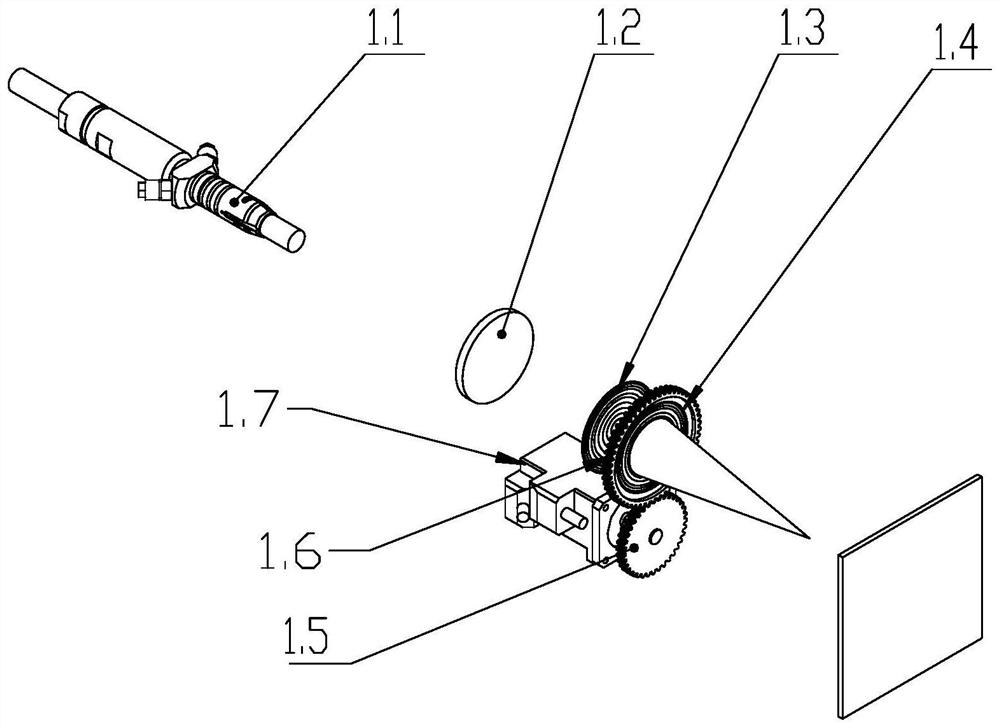
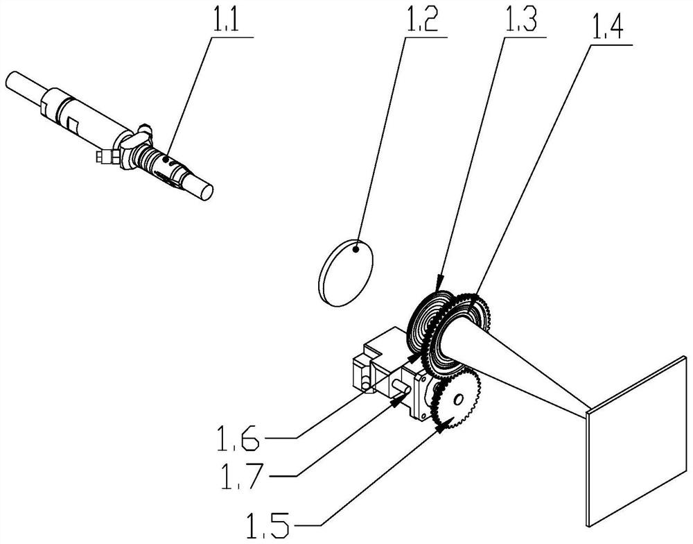
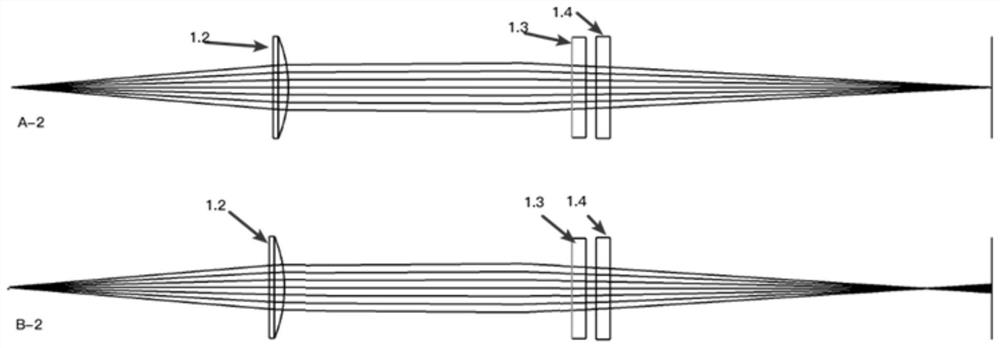
[0060] refer to figure 1 and 2 , this embodiment discloses a zoom laser processing system based on a variable spot diffraction element, including a laser 1.1 for generating laser light, a collimator lens 1.2 for changing the light path, and a diffractive optical element module for controlling the focus distribution of the spot, The collimating lens 1.2 is placed between the laser 1.1 and the diffractive optical element module, and the laser light emitted by the laser 1.1 is irradiated onto the diffractive optical element module through the collimating lens 1.2, and passes through the diffractive optical element The laser beam focused by the module is irradiated onto the workpiece to be processed, and the diffractive optical element module is used to control the focal power of the DOE lens and the focus distribution of the laser light, so that the focal point generated by the diffractive optical element module moves along a predetermined processing track to Complete the proces...

Embodiment 2

[0075] This embodiment only describes the differences from the above embodiments. In this embodiment, the drive shaft of the rotating drive motor 1.7 is connected to more than two driving gears 1.5, and the number of teeth and diameters of multiple driving gears 1.5 can be the same or different. Similarly, the rotation driving motor 1.7 drives one or more driving driving gears 1.5 to rotate, so that the driven driving gear 1.6 meshing with the driving driving gear 1.5 rotates at the same or different angles. In this embodiment, a diffractive optical element module composed of three or more DOE lenses can be constructed.

Embodiment 3

[0077] This embodiment discloses based on the same inventive concept, and the second purpose of the present invention is to provide a zoom laser processing method based on a variable spot diffraction element, including the following steps:

[0078] S1. Select a laser for generating laser light, a collimating lens for changing the light path, and a diffractive optical element module for controlling the focus distribution of the spot, and place the collimating lens between the laser and the diffractive optical element module , selecting different characteristic functions according to its lens array size, pixel size and zoom interval to set the lens profile function of the DOE lens;

[0079] S2. The diffractive optical element module selects at least two DOE lenses that are relatively distributed in the axial direction and a rotating drive that drives the DOE lenses to rotate, and at least one of the DOE lenses is driven by the rotating drive to capture the light of the DOE lens ...


PUM


Abstract

The invention discloses a zoom laser processing system and method based on a variable spot diffraction element. The system comprises a laser used for generating laser, a collimating lens used for changing a light path and a diffractive optical element module used for controlling spot focus distribution, and the laser emitted by the laser is irradiated to the diffractive optical element module through the collimating lens. The laser focused by the diffractive optical element module is emitted to a workpiece to be processed; and the diffractive optical element module comprises at least two DOE lenses oppositely distributed in the axial direction and a rotation driving part driving the DOE lenses to rotate, and the rotation driving part drives at least one DOE lens to rotate with the central axis as the rotation center, so the position of a focus generated after laser is focused through the diffractive optical element module is changed. According to the system, energy and the focus position of a light beam are dynamically adjusted through rotation of the DOE lens, so that a dynamic focus-adjustable quick response scheme is achieved, and laser machining is conducted on a workpiece to be machined through dynamic light spots.

Description

technical field [0001] The invention relates to the technical field of laser processing, in particular to a zoom laser processing system and method based on a variable spot diffraction element. Background technique [0002] In the field of laser processing, the existing methods of adjusting the laser focus are mostly realized by moving the lens along the axial direction, so that the focus can be dynamically changed. However, this adjustment method requires the installation of an axial displacement driver and the calculation of the axial displacement. The impact on the focus position and the axial displacement of the driving lens at the same time will inevitably increase the length of the entire laser processing equipment in the axial direction, making the size of the equipment larger, which is not suitable for laser processing equipment with a compact structure. Contents of the invention [0003] In order to solve the above-mentioned technical problems, the first object of...

Claims


Application Information

Patent Timeline
Patent Type & Authority Applications(China)
IPC IPC(8): B23K26/046B23K26/06B23K26/70
CPCB23K26/0648B23K26/046B23K26/702
Inventor 杜斌常勇
Owner FOSHAN HONGSHI LASER TECH CO LTD
Learn More