A thread automatic rotary mold ejector

An automatic rotation and thread technology, applied in the direction of threaded products, household appliances, other household appliances, etc., can solve the problems of reducing processing efficiency, product end fracture, affecting processing, etc., to ensure product efficiency, improve product quality, Good quality product

Active Publication Date: 2022-04-22
ZHENGZHOU XINJIEYE AUTOMOTIVE ELECTRONICS
View PDF10 Cites 0 Cited by
  • Summary
  • Abstract
  • Description
  • Claims
  • Application Information

AI Technical Summary

Problems solved by technology

[0003] Chinese invention patent CN201410780678.6 relates to the field of injection mold manufacturing, specifically the injection mold thread ejection mechanism, including a panel, a bottom plate, an upper mold, a lower mold, a fixing plate, an external threaded rod and a threaded mandrel, the panel and the upper mold are fixed, The externally threaded rod is fixed at the geometric center of the panel by screws, and the externally threaded rod passes through the upper mold, the lower mold fixing plate and the bottom plate in turn, and a ring gear containing internal threads is arranged between the fixing plate and the externally threaded rod. The rod portion of the threaded mandrel is connected to the fixed plate through a bearing, the driven gear is fixedly arranged on the rod portion of the threaded mandrel, a power gear is arranged between the driven gear and the ring gear, and the ring gear is also The threaded mandrel is connected to the fixed plate through a bearing, and the threaded mandrel is provided with threads on the top and forms an injection cavity with the upper mold; because the mold has an upper mold and a lower mold, there will be a parting line, which will seriously affect the aesthetics of the product
[0004] Because the product has an external thread structure, when the existing single cavity is manufactured, the product will stick to the cavity at the initial stage of mold release, so when the cavity rotates, it will drive the product to rotate accordingly, resulting in It is inconvenient to turn and eject the mold, and even cause the end of the product to break
[0005] At the same time, when the product breaks in the cavity, due to the thread fit between the external thread structure of the product and the internal thread structure of the cavity, the broken product will be inconvenient to leave the cavity, which will affect the subsequent processing
[0006] In the existing device, the damaged waste products and the intact products are often piled together in the recycling box after the mold is released, so it is necessary to manually sieve the waste products, which greatly increases the labor intensity and reduces the processing efficiency

Method used


Image

  • A thread automatic rotary mold ejector
  • A thread automatic rotary mold ejector
  • A thread automatic rotary mold ejector

Examples


no. 1 example

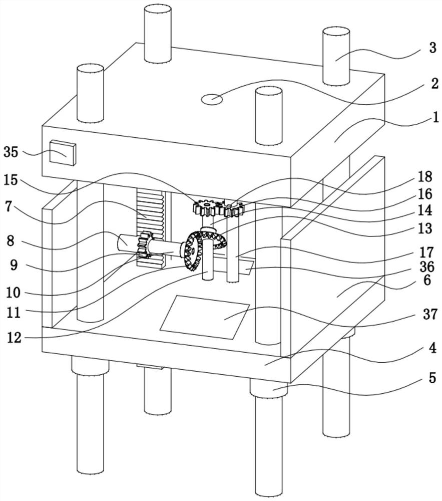
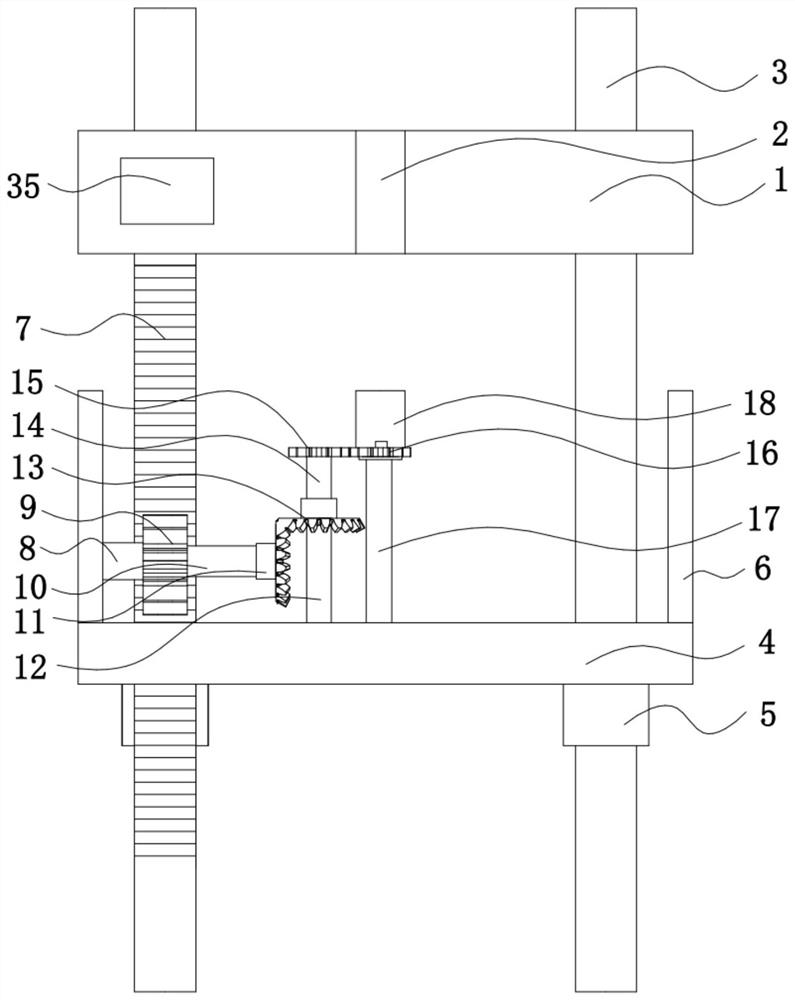
[0031] Such as Figure 1-3, a screw thread automatic rotary molding machine, including a static template 1, the static template 1 will not be displaced during the production process, and is in a static state, the static template 1 is opened with a glue injection port 2 inside, and the top of the glue injection port 2 is set There is a glue injection device, which directly injects glue into the glue injection port 2 to make the required external thread product. The inside of the glue injection device is equipped with a top glue needle. After the glue injection process is completed, the top glue The needle can eject the external thread product from the injection port 2, thereby facilitating unloading and improving processing efficiency. A controller 35 is provided on one side of the static template 1, and the controller 35 electrically controls each electrical component.

[0032] The bottom of the static template 1 is slidably connected with the movable template 4 through a slid...

no. 2 example

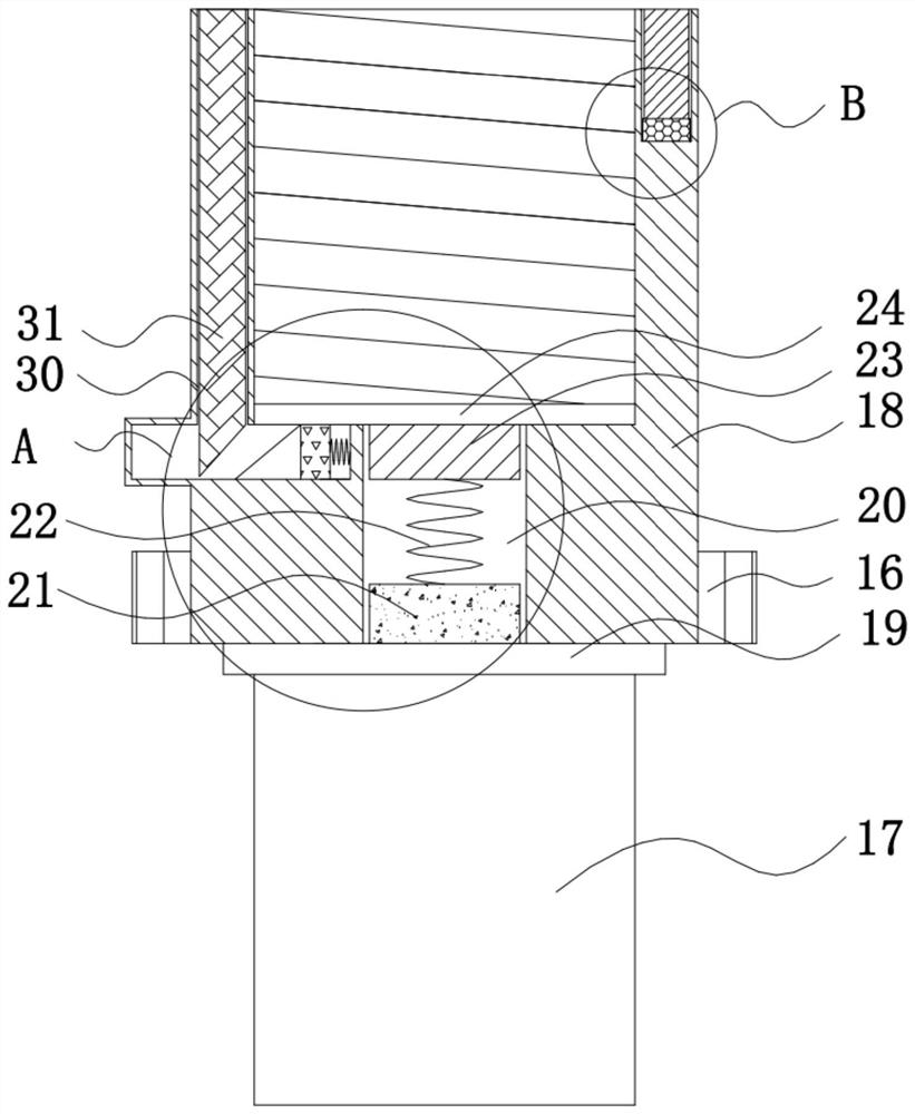
[0044] Such as Figure 3-7 , based on a screw thread automatic rotary mold ejector provided in the first embodiment, at the initial stage of mold ejection, since the rubber material adheres to the internal thread 29 inside the cavity 18, the cavity 18 is easy to drive the outer thread when the mold is ejected by rotation. The threaded product rotates synchronously with the rotation of the cavity 18, thereby causing inconvenience in mold release, and what is more, damage to the external thread product; at the same time, if the external thread product breaks during the injection process or when the mold is released, the waste product will remain It cannot be withdrawn inside the cavity 18, which will affect the subsequent glue injection production; and if the finished products and waste products are uniformly recycled after the mold is released, the products still need to be sorted manually, thereby reducing production efficiency. This problem ensures the stability of the device...


PUM


Abstract

The invention belongs to the technical field of screw thread ejection, in particular to a screw thread automatic rotary ejection machine, which includes a static template, which has a glue injection port inside, and a controller is provided on one side of the static template; The bottom of the static formwork is slidably connected with the movable formwork through a sliding device, and the bottom of the static formwork and the top of the movable formwork are provided with a cavity through a transmission part, and internal threads are provided inside the cavity; the top of the movable formwork is provided with A fixed column, the other end of the fixed column passes through the central axis of the cavity and is rotatably connected with the cavity through a support bearing, the top of the fixed column is dug with a first chute, and the inner bottom of the first chute Equipped with the first electromagnet, this device can not only realize single-cavity mold ejection, avoid parting line, improve the aesthetics of external thread products, but also eject the broken external thread products in the cavity to avoid its damage. It will affect the next injection, and can self-adaptively screen the external thread products to improve the efficiency of mold release.

Description

technical field [0001] The invention belongs to the technical field of thread ejection, in particular to a thread automatic rotary ejection machine. Background technique [0002] Mold Making refers to the processing of forming and billet tools, and also includes shearing dies and die-cutting dies. Usually, the mold consists of two parts, the upper mold and the lower mold. The steel plate is placed between the upper and lower molds, and the material is formed under the action of the press. When the press is opened, the workpiece determined by the shape of the mold will be obtained or the corresponding waste will be removed; as small as an electronic connector, as large as The workpieces of automobile dashboards can be molded. Progressive die refers to a set of molds that can automatically move the workpiece from one station to another, and obtain formed parts at the last station; mold processing technology includes: cutting die, punching die, composite die , extrusion die,...

Claims


Application Information

Patent Timeline
Patent Type & Authority Patents(China)
IPC IPC(8): B29C45/40B29C45/26B29C45/27B29L1/00
CPCB29C45/40B29C45/2602B29C45/2618B29C45/27B29L2001/00
Inventor 郭文明高军华刘梦雅刘秀娟
Owner ZHENGZHOU XINJIEYE AUTOMOTIVE ELECTRONICS
Why Eureka
Try Eureka