Underwater cleaning robot
A technology of robots and machine bases, applied in underwater operation equipment, ship cleaning devices, ships, etc., to achieve the effect of saving operation steps and reducing work efficiency
- Summary
- Abstract
- Description
- Claims
- Application Information
AI Technical Summary
Problems solved by technology
Method used
Image
Examples
Embodiment 1
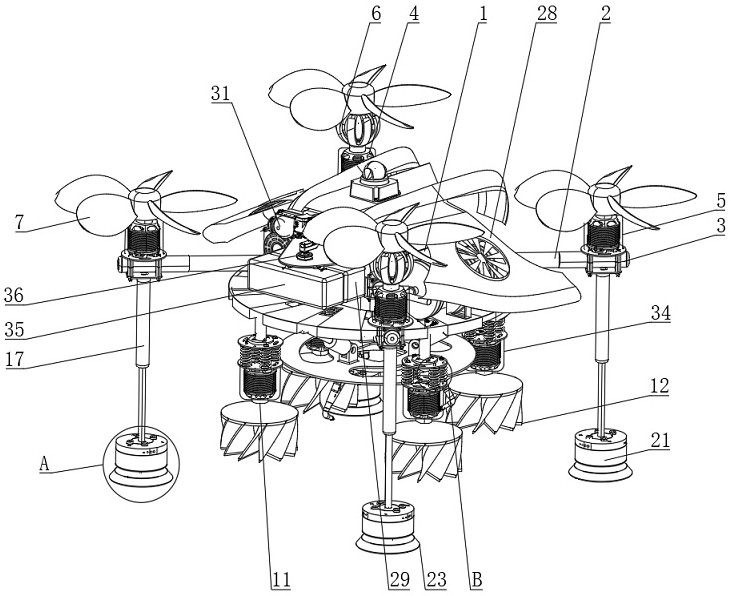
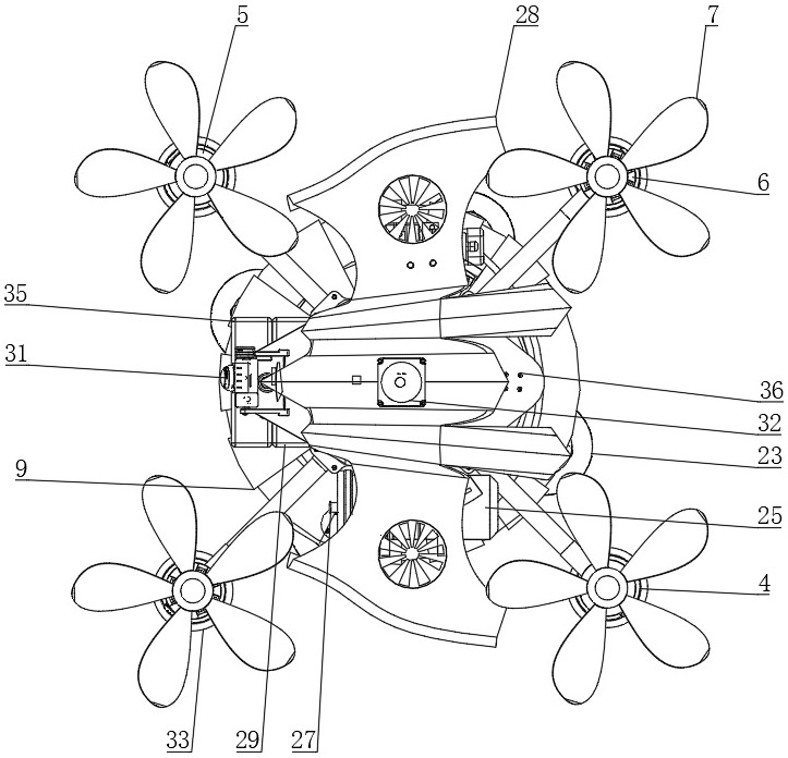
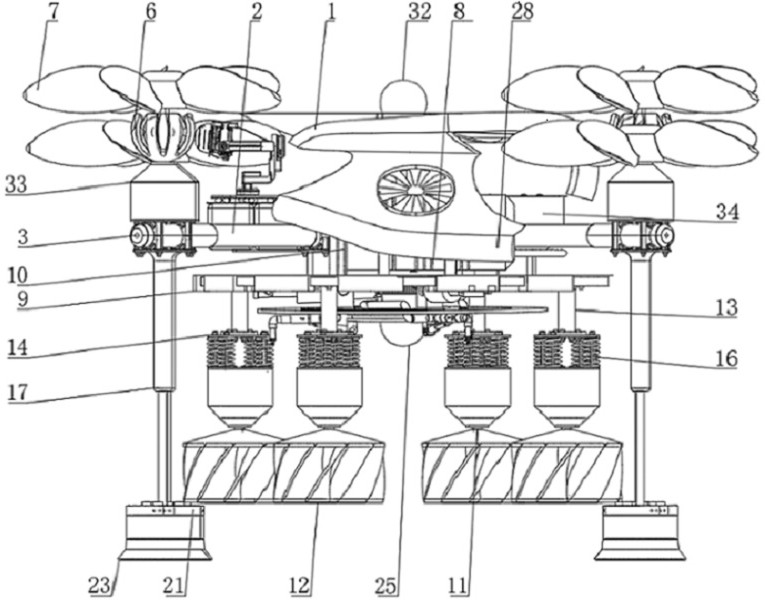
[0040] see Figure 1-9, an underwater cleaning robot, including a base 1 and a control center 8 installed on the base 1, a running mechanism, and a cleaning mechanism, the running mechanism includes: a plurality of thrusters installed on the base 1; a telescopic mechanism installed on the Between at least one propeller and the base 1; the electromagnetic adsorption mechanism is installed on the propeller. When working, the propeller is controlled by the control center 8 to rotate, and the propeller applies an upward lift to the base 1 to relieve the gravity of the robot, and then Put the robot into the water and stir the water flow through the propeller, so that the robot is subjected to the reaction force of the water flow and moves to the outer surface of the hull. At the same time, the intermittent movement of the propeller and the running mechanism is controlled by the control center 8, so that the propeller and the running mechanism are supported. At the same time, the ro...
Embodiment 2
[0042] refer to figure 1 and image 3 , the propellers are distributed in pairs on opposite sides of the base 1, at least one pair of propellers includes a plurality of servo motors 4 arranged outside the base 1, one end of the servo motors 4 is connected to the telescopic mechanism, and the output end of the servo motors 4 Equipped with a reducer 5, the end of the reducer 5 away from the servo motor 4 is rotated and installed with a propeller 7, the two reducers 5 and the propeller 7 are rotationally connected by a universal joint 6, and the control center 8 is electrically connected to the servo motor 4. The lower end of the machine base 1 is provided with a cleaning mechanism located outside the control center 8, and the lower end of the cross bar 3 is provided with an adsorption mechanism. When working, the control center 8 controls the operation and parking of the servo motor 4, so that the servo motor 4 can be decelerated The propeller 5 drives the propeller 7 to rotate...
Embodiment 3
[0053] The propellers are distributed in a "ten" shape, and two universal joints 6 are respectively arranged at two opposite corners of the machine base 1. When the robot needs to turn, the attitude of the corresponding propellers is changed through the two universal joints 6, so that the two The opposite propeller supports the robot to suspend, while the other two relative propellers apply steering force to the robot until the robot rotates to the specified position, and then reset the propeller to the initial position through the universal joint 6, and finally all the propellers apply buoyancy to the robot .
[0054] Working principle: When working, control the rotation of the propeller through the control center 8, and the propeller applies an upward lift force to the machine base 1 to relieve the gravity of the robot, then put the robot into the water, and stir the water flow through the propeller, so that the robot is affected by the water flow. The reaction force moves t...
PUM
 Abstract
Description
Claims
Application Information
 - R&D
- Intellectual Property
- Life Sciences
- Materials
- Tech Scout
- Unparalleled Data Quality
- Higher Quality Content
- 60% Fewer Hallucinations
Browse by: Latest US Patents, China's latest patents, Technical Efficacy Thesaurus, Application Domain, Technology Topic, Popular Technical Reports.
© 2025 PatSnap. All rights reserved.Legal|Privacy policy|Modern Slavery Act Transparency Statement|Sitemap|About US| Contact US: help@patsnap.com


