

Card feeding device and in-vitro diagnosis equipment
A card feeding and hooking technology, which is applied in the direction of analyzing materials and instruments, can solve the problems of reagent card mis-insertion, etc., and achieve the effects of low production cost, simplified structure and long service life
- Summary
- Abstract
- Description
- Claims
- Application Information
AI Technical Summary
Problems solved by technology
Method used
Image

Examples
Embodiment Construction
[0025] In order to make the purpose, technical solution and advantages of the present invention clearer, the technical solution of the present invention will be clearly and completely described below in conjunction with specific embodiments of the present invention and corresponding drawings. Apparently, the described embodiments are only some of the embodiments of the present invention, but not all of them. Based on the embodiments of the present invention, all other embodiments obtained by persons of ordinary skill in the art without making creative efforts belong to the protection scope of the present invention, and the parts not mentioned in the present invention are all prior art. The technical solutions provided by various embodiments of the present invention will be described in detail below in conjunction with the accompanying drawings.
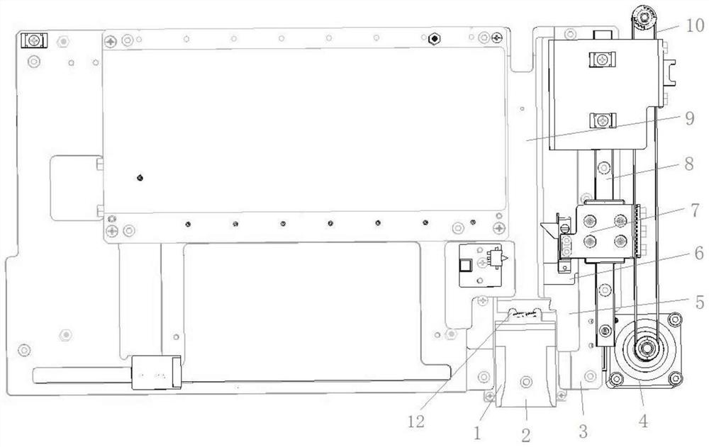
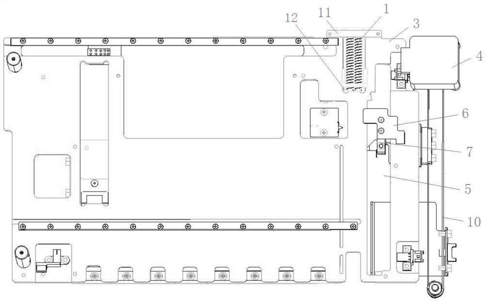
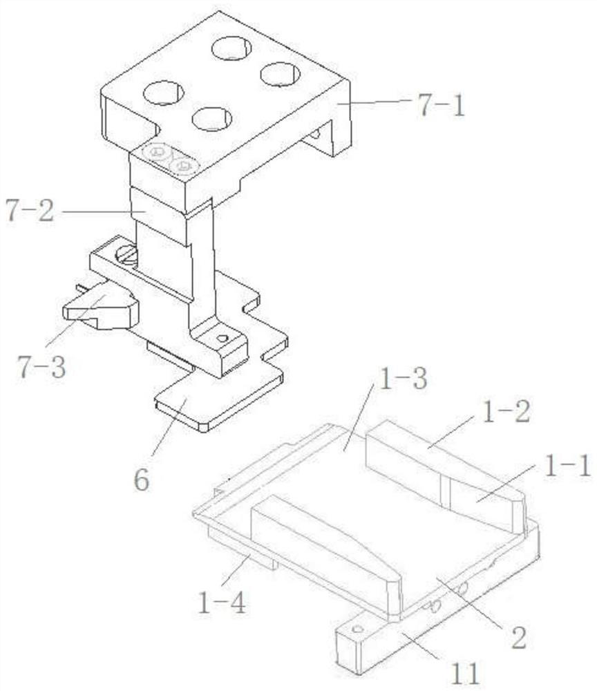
[0026] see Figure 1 to Figure 2 , a kind of card-feeding device, comprises card-feeding channel 9, the card-feeding mouth 2 that i...
PUM
 Abstract
Description
Claims
Application Information