Laser radar

A laser radar and laser receiving technology, applied in radio wave measurement systems, instruments, etc., can solve problems such as difficulty in mass production and short distance measurement, and achieve the effects of low cost, simple overall processing, and reduced load

Inactive Publication Date: 2022-01-28
TANWAY TECH (BEIJING) CO LTD
View PDF15 Cites 0 Cited by
  • Summary
  • Abstract
  • Description
  • Claims
  • Application Information

AI Technical Summary

Problems solved by technology

However, due to its own technical bottlenecks, solid-state radar has many problems such as difficulty in mass production and short range measurement.

Method used


Image

  • Laser radar
  • Laser radar
  • Laser radar

Examples


Embodiment Construction

[0037] In order to make the purpose, technical solution and advantages of the present invention clearer, the technical solution of the present invention will be clearly and completely described below in conjunction with the accompanying drawings. Apparently, the described embodiments are some, but not all, embodiments of the present invention. Based on the embodiments of the present invention, all other embodiments obtained by persons of ordinary skill in the art without making creative efforts belong to the protection scope of the present invention.

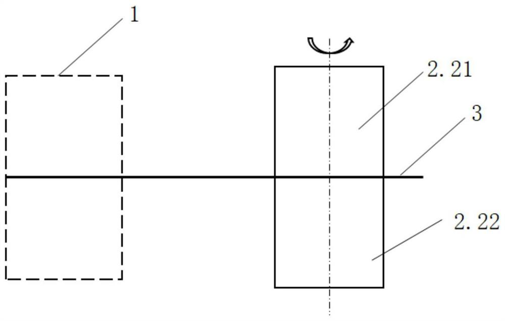
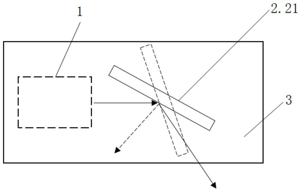
[0038] In the description of the present invention, it should be noted that the orientation or positional relationship indicated by the terms "upper", "lower", "front", "rear" etc. is based on the orientation or positional relationship shown in the drawings, in this example The directions perpendicular to the propagation direction of the optical path are respectively defined as front and rear, which are only for the convenience ...


PUM


Abstract

The invention relates to a laser radar, which comprises a laser emitting mechanism, a laser receiving mechanism and a light scanning mechanism. The laser emitting mechanism and the laser receiving mechanism are longitudinally isolated. The light scanning mechanism comprises a reflecting mirror mechanism and a motor, the reflecting mirror mechanism is installed on the motor, the motor drives the reflecting mirror mechanism to rotate, and the reflecting mirror mechanism is longitudinally divided into a transmitting end reflecting mirror and a receiving mirror. The laser emitting mechanism emits linear laser with a preset angle. The linear laser is reflected to a detected object through the transmitting end reflecting mirror, the detected object performs diffuse reflection on the light, and the light subjected to diffuse reflection is reflected back to the laser receiving mechanism by the receiving mirror to complete measurement. The system is stable and miniaturized through the arrangement and assembly mode of the system, and the requirement for a large view field can be met.

Description

technical field [0001] The present invention relates to the technical field of laser radar, in particular to a laser radar that achieves system stability, miniaturization and can meet the requirement of a large field of view through the arrangement and assembly of the system. Background technique [0002] At present, most of the lidars used are mechanical rotary lidar, hybrid solid-state lidar and solid-state lidar. The internal mechanism part of the lidar usually includes three important modules, namely: laser emission, laser reception, and light scanning. The three modules constitute the main system of the radar. [0003] Among them, the mechanical rotary laser radar generally fixes the laser emission and reception on the motor for fixed-axis rotation, and achieves the effect of scanning the entire field of view through the 360° rotation of the motor. However, in this way, the motor load is relatively large, and the motor The requirements for bearings and shafts are highe...

Claims


Application Information

Patent Timeline
Patent Type & Authority Applications(China)
IPC IPC(8): G01S7/481G01S7/483G01S7/495
CPCG01S7/481G01S7/483G01S7/495
Inventor 王茜茜张正杰沈罗丰王世玮郑睿童
Owner TANWAY TECH (BEIJING) CO LTD
Why Eureka
Try Eureka