Layer-stranded rat-bite-proof optical cable
A rat-proof, layer-twisting technology, applied in the directions of light guides, optics, optical components, etc., can solve the problems of easily crushing the internal optical fiber, unable to achieve rodent repelling, etc., to enhance strength, prevent bending, and buffer extrusion. Effect
- Summary
- Abstract
- Description
- Claims
- Application Information
AI Technical Summary
Problems solved by technology
Method used
Image

Examples
Embodiment 1
[0025] Embodiment one, combining Figure 1-Figure 4 Be explained:
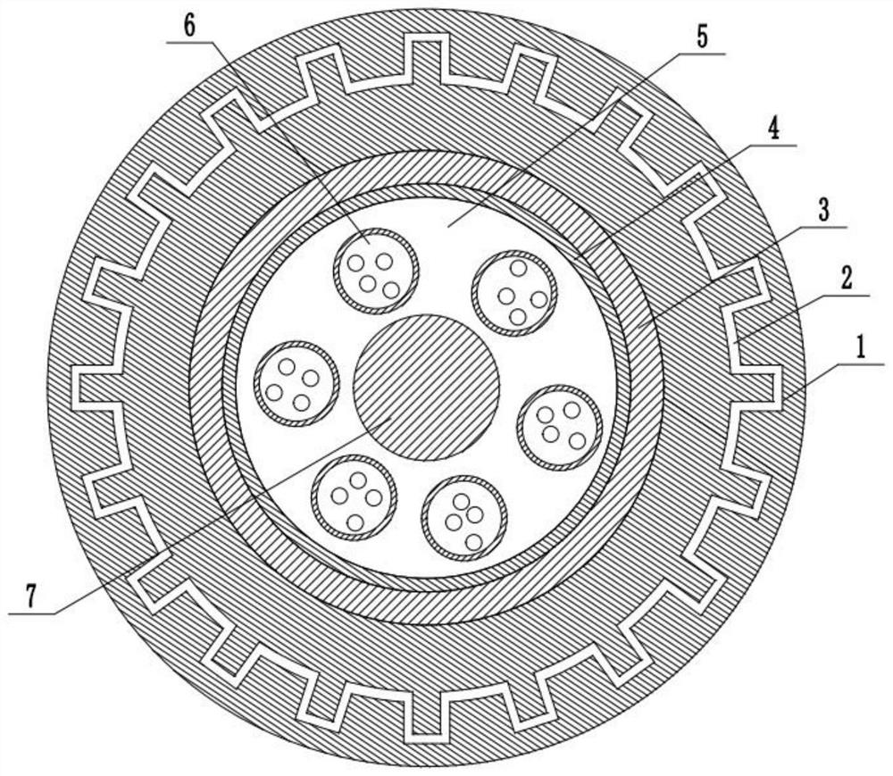
[0026] A layer-twisted anti-rat-biting optical cable, comprising: a protective jacket 1, a yarn binding layer 4, a cable core filling glue 5, an optical fiber 6 and a reinforcing steel wire 7, the protective jacket 1 is coaxially provided with a yarn binding layer 4, and the yarn binding layer 4 The yarn layer 4 is filled with a cable core filling glue 5, and a plurality of optical fibers 6 are arranged in the cable core filling glue 5, and a reinforcing steel wire 7 is coaxially arranged in the protective jacket 1, and the reinforcing steel wire 7 is located in the cable core filling glue 5. A composite steel belt 3 is arranged between the binding yarn layer 4 and the protective jacket 1, a rat-repelling layer 2 is arranged inside the protective jacket 1, an optical fiber 6 is arranged around a reinforcing steel wire 7, the protective jacket 1 is made of rubber, and an anti Rat masterbatch, reinforced steel ...
Embodiment 2
[0027] Embodiment two, combining Figure 1-Figure 4 Be explained:
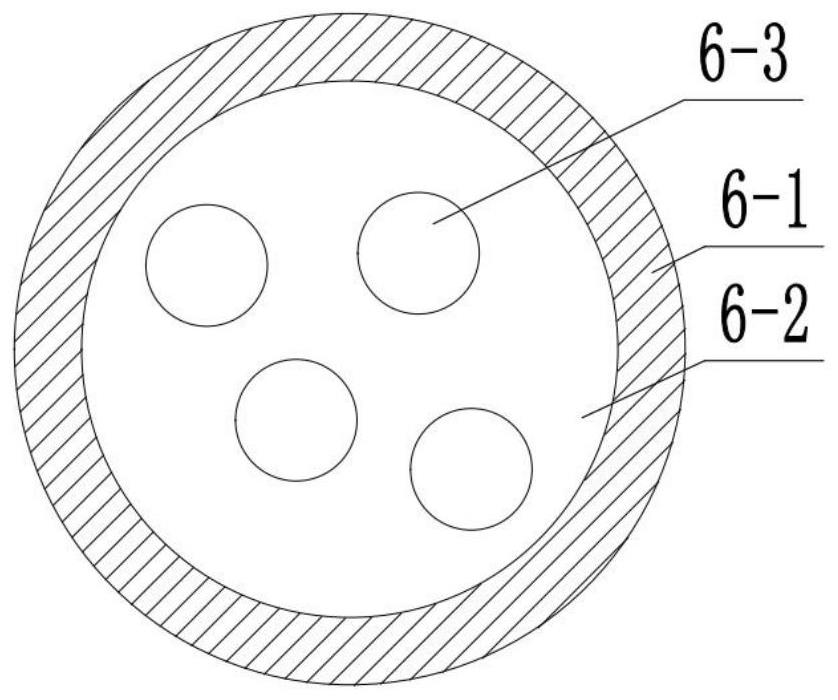
[0028] The optical fiber 6 includes: a loose tube 6-1, a fiber inner filler 6-2 and an optical fiber body 6-3, the loose tube 6-1 is located in the cable core filler 5, and the loose tube 6-1 is Filled with the fiber filling glue 6-2, the fiber body 6-3 is located in the fiber filling glue 6-2.
Embodiment 3
[0029] Embodiment three, combining Figure 1-Figure 4 Be explained:
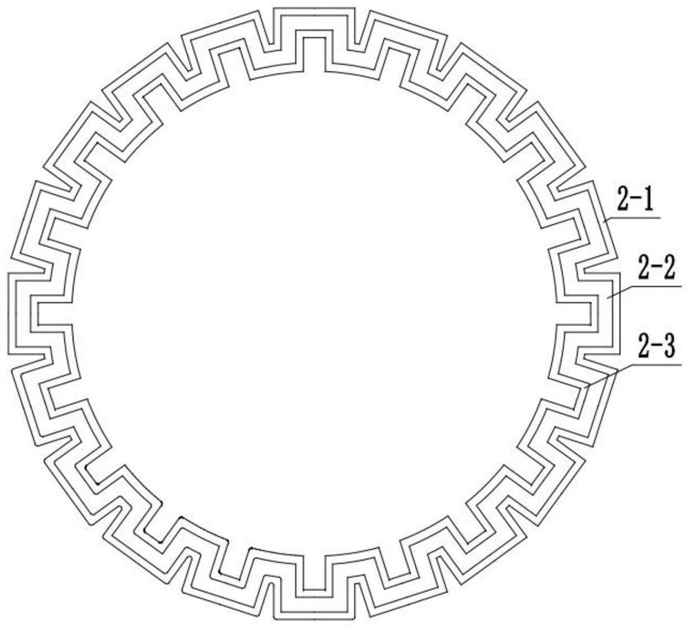
[0030] The rodent repelling layer 2 includes wrapped iron net A2-1, filled camphor 2-2, wrapped iron net B2-3, wrapped iron net A2-1 and wrapped iron net B2-3 are coaxially arranged on the protective jacket 1, so A cavity is formed between the wrapped iron net A2-1 and the wrapped iron net B2-3, and the filled camphor 2-2 is arranged in the cavity. The wrapped iron net A2-1 leaked, and the filling of camphor 2-2 can release the unpleasant smell of mice, and play the function of dispersing the rats, while the wrapped iron net A2-1 and wrapped iron net B2-3 have the characteristics of being relatively hard. After camphor 2-2 loses its effect, it plays the role of bite resistance.
[0031] Working principle of the present invention:
[0032] Because the anti-rat masterbatch is added in the protective coat 1, it can play a role in dispersing the rats. When the anti-rat masterbatch loses its effectiveness and ...
PUM
 Abstract
Description
Claims
Application Information
 - R&D
- Intellectual Property
- Life Sciences
- Materials
- Tech Scout
- Unparalleled Data Quality
- Higher Quality Content
- 60% Fewer Hallucinations
Browse by: Latest US Patents, China's latest patents, Technical Efficacy Thesaurus, Application Domain, Technology Topic, Popular Technical Reports.
© 2025 PatSnap. All rights reserved.Legal|Privacy policy|Modern Slavery Act Transparency Statement|Sitemap|About US| Contact US: help@patsnap.com