Supercharge Your Innovation With Domain-Expert AI Agents!

Modularized error code testing device

A bit error testing and modularization technology, applied in the field of communication, can solve problems such as connector falling off, failure to ensure consistency, damage to connector connection strength, etc., to achieve enhanced deformability, avoid unqualified appearance, and ensure close contact.

Active Publication Date: 2022-01-28
STELIGHT INSTR CO LTD
View PDF5 Cites 3 Cited by
  • Summary
  • Abstract
  • Description
  • Claims
  • Application Information

AI Technical Summary

Problems solved by technology

[0003] Generally, the connector is welded on the test board body, and the test board with pluggable connectors can be compatible with different optical modules to be tested, and different optical modules to be tested may have dimensional errors during manufacture. Moreover, when inserting different optical modules to be tested into the connectors by hand or with a robot, it is impossible to ensure that the insertion positions of each optical module to be tested are consistent. Ensure that the insertion height of the optical module to be tested corresponds to the predetermined height of the connector, causing the insertion of the optical module to be tested to generate a force on the connector. This force will damage the welding stability of the connector and may damage the connection strength of the connector. Cause the connector to fall off, affect the service life of the connector, or fail to maintain a normal connection with each optical module to be tested, and also affect the appearance quality of the optical module to be tested. Poor contact will affect the signal integrity and cause the test to fail.

Method used


Image

  • Modularized error code testing device
  • Modularized error code testing device
  • Modularized error code testing device

Examples


Embodiment Construction

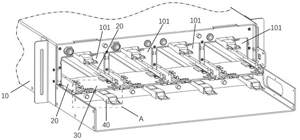
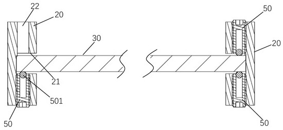
[0052] figure 1 It is a schematic diagram of a partial structure of a modular error testing device according to an embodiment of the present invention. figure 2 yes figure 1 Partial enlarged view of A in the center. image 3 is a schematic cross-sectional view of the modularized bit error testing device at the ball plunger 50 according to an embodiment of the present invention. Figure 4 It is a structural schematic diagram of an optical module 40 to be tested in a modularized bit error testing device according to an embodiment of the present invention. Figure 5 It is a structural schematic diagram of a test board 30 of a modular error testing device according to an embodiment of the present invention. Such as figure 1As shown, in one embodiment, the modularized bit error testing device includes a tester box 10, a channel rail 20, a test board 30 and a ball plunger 50 (see image 3 ). The tester case 10 is formed with a plurality of installation cavities 101 extending ...


PUM


Abstract

The invention provides a modularized error code testing device,which belongs to the technical field of communication. The modularized error code testing device comprises a tester box body and a horizontally arranged test board for insertion, wherein the tester box body is provided with a plurality of installation cavities extending along the length direction of the tester box body, the front end of each installation cavity is provided with an installation opening, the two sides of each installation cavity are provided with channel guide rails, and the sides, facing each other, of the two channel guide rails in each installation cavity are provided with installation grooves; one end of the test board in the length direction is fixed with the box body, the other end of the test board is provided with a connector used for inserting a to-be-tested optical module, the position, close to the connector, of each channel guide rail is provided with a vertically-arranged through hole used for installing a ball head plunger, the ball head end of the ball head plunger abuts against the test board, and a plurality of micro holes for increasing the flexibility of the test board are formed in the preset area of the test board. The modularized error code testing device can ensure that different optical modules to be tested are in good contact with the connector.

Description

technical field [0001] The invention relates to the technical field of communications, in particular to a modular error code testing device. Background technique [0002] The test board of the bit error tester is provided with a connector for connecting the optical module to be tested. After the optical module to be tested is plugged into the connector, the bit error tester can test the optical module to be tested. In order to keep the optical module under test working normally during the test, it is necessary to keep the optical module under test and the connector connected normally. Usually, the test board with the connector is first fixed on the fixture base, and the golden finger of the optical module to be tested is inserted into the connector on the test board. [0003] Generally, the connector is welded on the test board body, and the test board with pluggable connectors can be compatible with different optical modules to be tested, and different optical modules to b...

Claims


Application Information

Patent Timeline
Patent Type & Authority Applications(China)
IPC IPC(8): H04B10/079H05K7/20
CPCH04B10/0795H05K7/20H05K7/20272H05K7/20254Y02E10/50
Inventor 周晓峰范学斌邓仁辉
Owner STELIGHT INSTR CO LTD
Features
  • R&D
  • Intellectual Property
  • Life Sciences
  • Materials
  • Tech Scout
  • Unparalleled Data Quality
  • Higher Quality Content
  • 60% Fewer Hallucinations
Learn More