Control method and device of wireless routing equipment and wireless routing equipment
A technology of equipment and lines, which is applied in the control of wireless routing equipment and in the field of wireless routing equipment, can solve the problems of increasing product power consumption and excessive radiation, so as to improve effective utilization, reduce power loss and radiation, and improve anti-interference ability Effect
- Summary
- Abstract
- Description
- Claims
- Application Information
AI Technical Summary
Problems solved by technology
Method used
Image

Examples
Embodiment Construction
[0039] Exemplary embodiments of the present disclosure will be described in more detail below with reference to the accompanying drawings. Although exemplary embodiments of the present disclosure are shown in the drawings, it should be understood that the present disclosure may be embodied in various forms and should not be limited by the embodiments set forth herein. Rather, these embodiments are provided for more thorough understanding of the present disclosure and to fully convey the scope of the present disclosure to those skilled in the art.
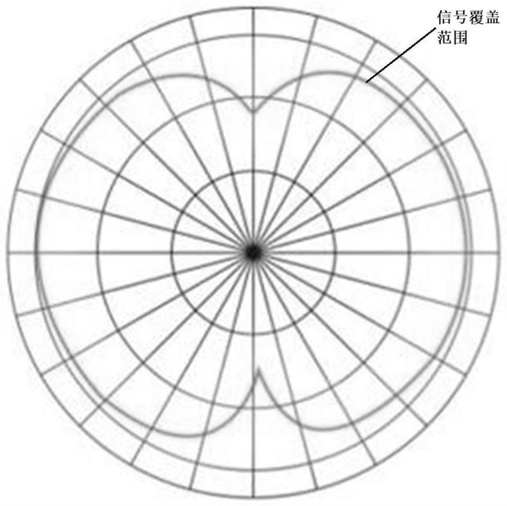
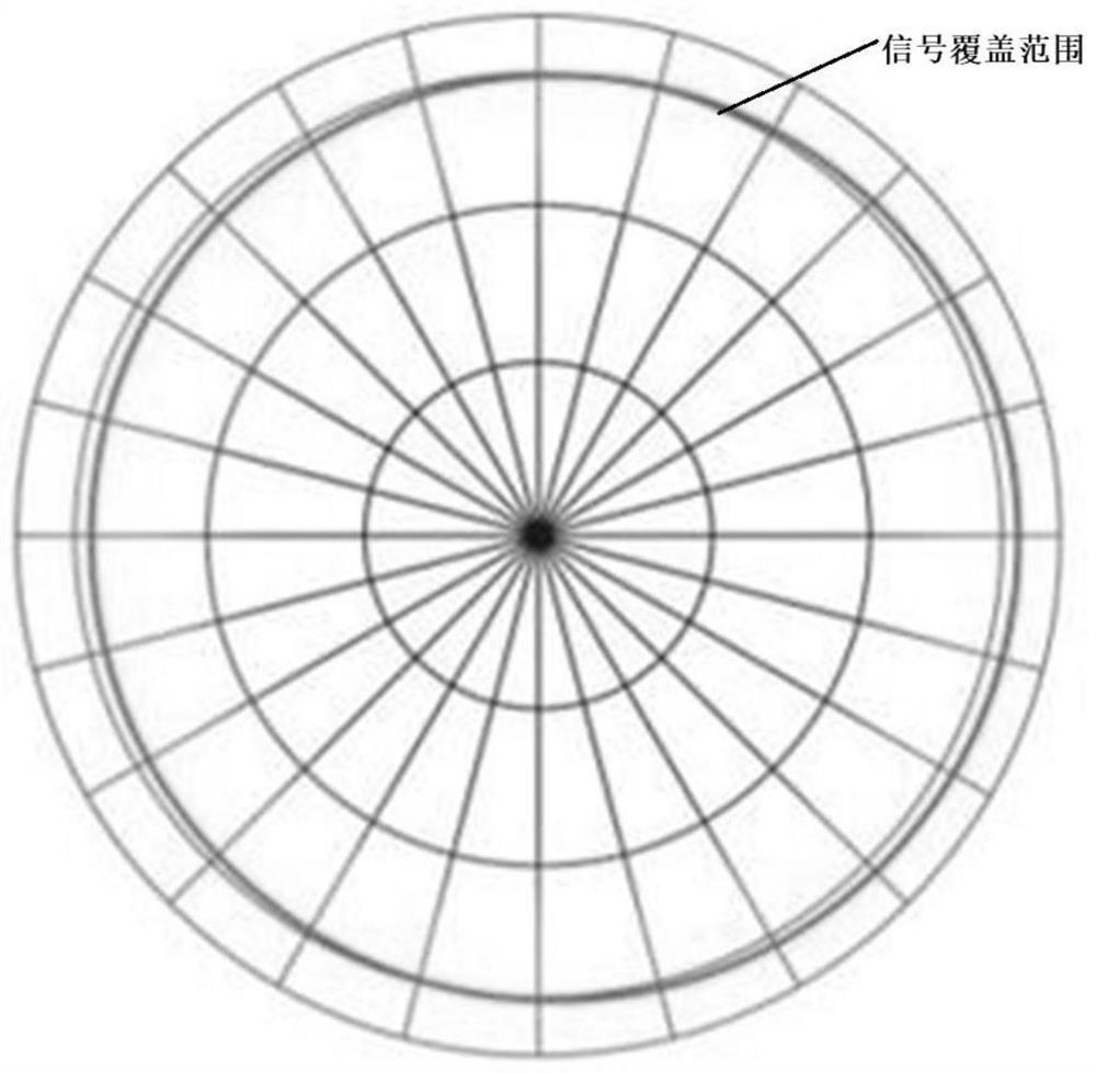
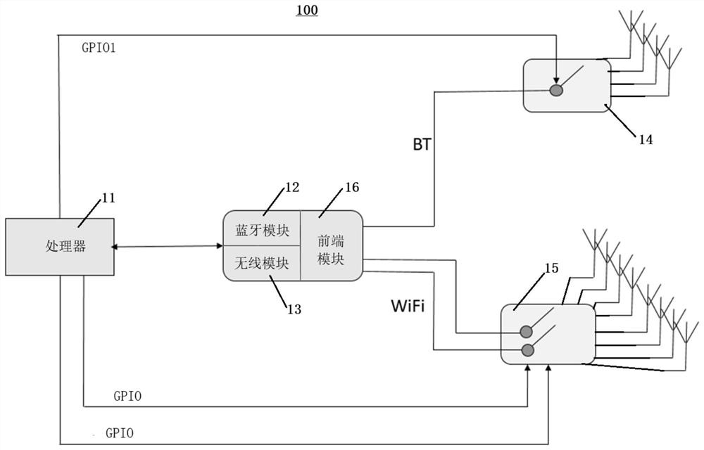
[0040] Embodiments of the present invention provide a method and device for controlling wireless routing equipment, which can be applied to directional signal transmission control of wireless routing equipment. The wireless routing device in this embodiment is at least provided with a Bluetooth array antenna and a wireless array antenna, and the wireless routing device includes but is not limited to routers, other devices with WIFI ...
PUM
 Abstract
Description
Claims
Application Information
PatSnap Eureka turns technology decisions into work you can execute. Powered by our Innovation Knowledge Graph, it runs expert workflows across engineering, life sciences, materials and intellectual property. Get your review-ready output in minutes.


