Lathe with waste collecting function

A waste collection and function technology, applied in the field of lathes, can solve problems such as blockage and affect the normal use of the lathe, and achieve the effect of avoiding blockage and reducing the pressure of manual work.

Inactive Publication Date: 2022-02-01
江先庆
View PDF0 Cites 2 Cited by
  • Summary
  • Abstract
  • Description
  • Claims
  • Application Information

AI Technical Summary

Problems solved by technology

[0004] The purpose of the present invention is to solve the shortcomings of the existing lathes that produce more debris and waste during the processing process, which needs to be cleaned regularly, otherwise it will cause blockage and affect the normal use of the lathe, and proposes a waste collection function. lathe

Method used


Image

  • Lathe with waste collecting function
  • Lathe with waste collecting function
  • Lathe with waste collecting function

Examples


Embodiment 1

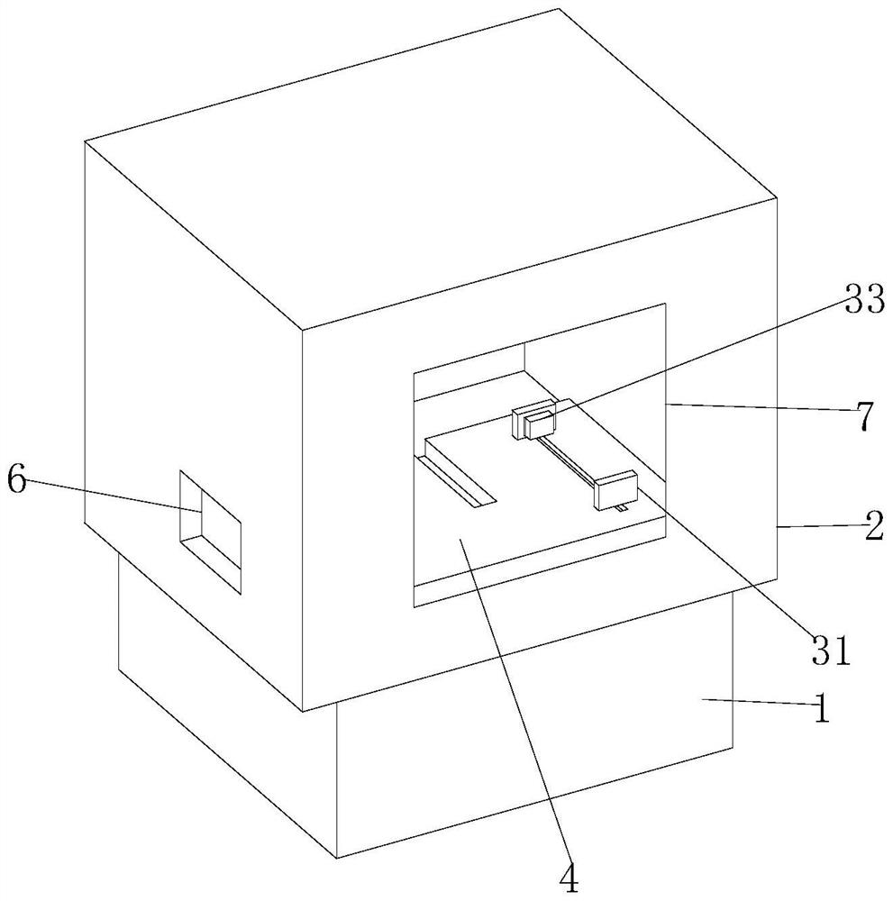
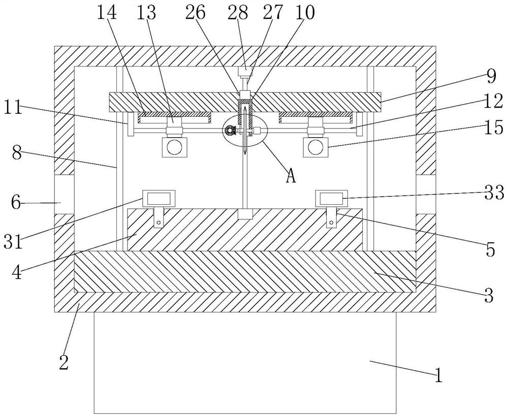
[0027] refer to Figure 1-7 , a lathe with waste collection function, comprising a base 1, the top of the base 1 is fixedly connected with an outer protective cover 2, the bottom inner wall of the outer protective cover 2 is fixedly provided with a backing plate 3, and the top of the backing plate 3 is fixedly arranged There is a workbench 4, and two chutes 5 are provided on the workbench 4, and a clamping mechanism is arranged in the chute 5. The left and right sides of the outer protective cover 2 are provided with feed troughs 6, and one side of the outer protective cover 2 is provided with The glass window 7 and the top of the backing plate 3 are fixedly connected with four limit rods 8, and the sliding sleeves on the four limit rods 8 are provided with the same limit top plate 9, and the bottom of the limit top plate 9 is fixedly connected with an installation sleeve 10, The installation cover 10 is provided with a cutting mechanism, the bottom of the limit top plate 9 is...

Embodiment 2

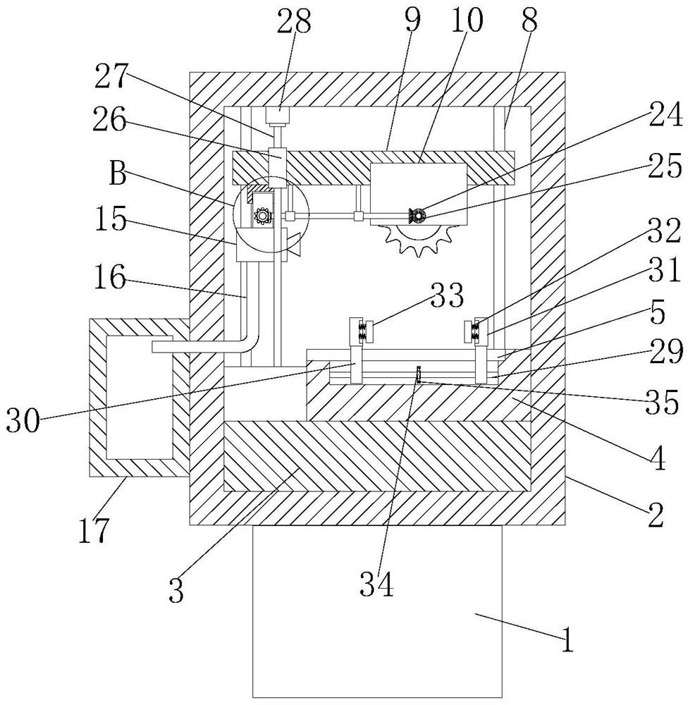
[0039] The difference from Embodiment 1 is that the chain 35 is connected with a second sprocket 36, the second sprocket 36 is fixedly sleeved with a linkage shaft 37, and one end of the linkage shaft 37 is fixedly connected with a third bevel gear 38. The third bevel gear 38 is meshed with a fourth bevel gear 39, and the fourth bevel gear 39 is fixedly sleeved on the drive screw 27. By setting the fourth bevel gear 39, the third bevel gear 38 can be rotated, and the second sprocket 36 The fixed sleeve is provided with a trigger shaft 40 , and a knob 41 is fixedly connected to the trigger shaft 40 .

[0040] Working principle, when in use, the workpiece is first placed on the workbench 4 through the trough 6 on the outer protective cover 2, and then the first motor 21 is started, and the first motor 21 can rotate the rotating shaft 22. Grinding wheel 23 just can cut workpiece, and the first bevel gear 24 on the rotating shaft 22 can rotate the second bevel gear 25 and connecti...


PUM


Abstract

The invention belongs to the technical field of lathes, and particularly relates to a lathe with a waste collecting function. The lathe comprises a base, wherein an outer protective cover is fixedly connected to the top of the base, a base plate is fixedly arranged on the inner wall of the bottom of the outer protective cover, a workbench is fixedly arranged on the top of the base plate, two sliding grooves are formed in the workbench, clamping mechanisms are arranged in the sliding grooves, material grooves are formed in the left side and the right side of the outer protective cover, a glass window is arranged on one side of the outer protective cover, four limiting rods are fixedly connected to the top of the base plate, the four limiting rods are slidably sleeved with the same limiting top plate, a mounting sleeve is fixedly connected to the bottom of the limiting top plate, a cutting mechanism is arranged in the mounting sleeve, the bottom of the limiting top plate is fixedly connected with two lug plates, and the two lug plates are rotationally connected with the same upper screw. Through cooperation of the upper screw and the upper screw sleeve, a suction fan can be continuously pushed to slide back and forth, scrap waste generated by the workbench can be conveniently recycled through the suction fan, and convenience and effectiveness are achieved.

Description

technical field [0001] The invention belongs to the technical field of lathes, in particular to a lathe with the function of collecting waste materials. Background technique [0002] A lathe is a machine tool that mainly uses a turning tool to turn a rotating workpiece. Drills, reamers, reamers, taps, dies and knurling tools can also be used for corresponding processing on the lathe. [0003] However, the existing lathes will generate more debris and waste during the processing process, which needs to be cleaned regularly, otherwise it will cause blockage and affect the normal use of the lathe. Contents of the invention [0004] The purpose of the present invention is to solve the shortcomings of the existing lathes that produce more debris and waste during the processing process, which needs to be cleaned regularly, otherwise it will cause blockage and affect the normal use of the lathe, and proposes a waste collection function. lathe. [0005] In order to achieve the ...

Claims


Application Information

Patent Timeline
Patent Type & Authority Applications(China)
IPC IPC(8): B24B27/06B24B47/12B24B47/16B24B47/20B24B55/06B24B55/12
CPCB24B27/0683B24B55/06B24B55/12B24B47/20B24B47/12B24B47/16
Inventor 江先庆
Owner 江先庆
Why Eureka
Try Eureka