
Cutting device with cutters convenient to disassemble

A technology that facilitates the disassembly and cutting of the device, which is applied to the device for coating liquid on the surface, transportation and packaging, and metal processing. It can solve the problems of inconvenient disassembly of the cutter, difficulty in controlling the size of the paper cut, and inconvenient distance between the two cutters. , to achieve the effect of strengthening the connection, facilitating cutting and processing, and facilitating installation and disassembly

Active Publication Date: 2022-02-01
东台骏兴科技有限公司
View PDF8 Cites 0 Cited by
  • Summary
  • Abstract
  • Description
  • Claims
  • Application Information

AI Technical Summary

Problems solved by technology

[0003] The object of the present invention is to provide a cutting device that facilitates disassembly of the cutter, so as to solve the problem that the cutter on the existing cutting device proposed in the above-mentioned background technology is inconvenient to disassemble , and it is inconvenient to adjust the distance between the two cutters according to the requirements, so it is difficult to control the cutting size of the paper, and it is inconvenient to automatically collect leftovers and finished products

Method used


Image

  • Cutting device with cutters convenient to disassemble
  • Cutting device with cutters convenient to disassemble
  • Cutting device with cutters convenient to disassemble

Examples


Embodiment Construction

[0038] The following will clearly and completely describe the technical solutions in the embodiments of the present invention with reference to the accompanying drawings in the embodiments of the present invention. Obviously, the described embodiments are only some, not all, embodiments of the present invention. Based on the embodiments of the present invention, all other embodiments obtained by persons of ordinary skill in the art without making creative efforts belong to the protection scope of the present invention.

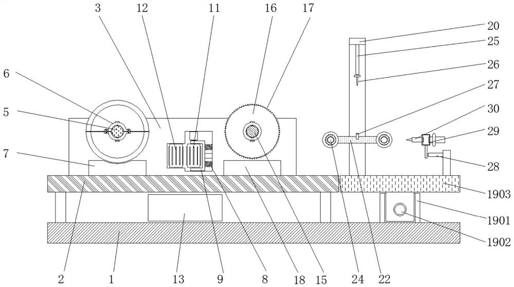
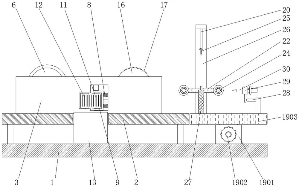
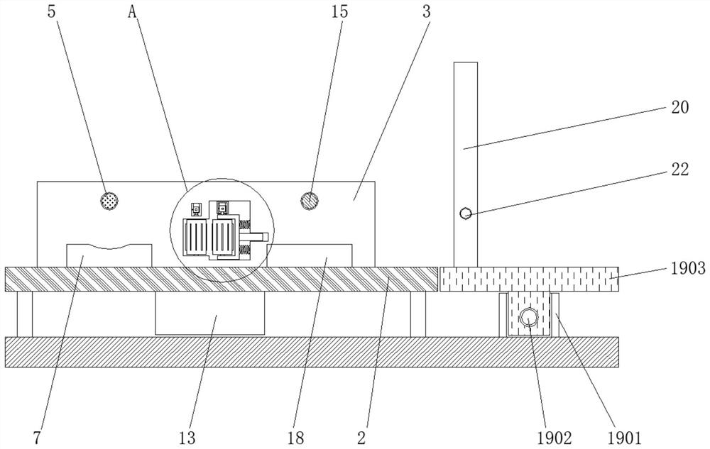
[0039] see Figure 1-6 , the present invention provides a technical solution: a cutting device that facilitates disassembly of the cutter, according to figure 1 As shown, the first bearing platform 2 is fixed on one side of the upper end surface of the base 1, and support plates 3 are symmetrically fixed on both sides of the upper end surface of the first bearing platform 2, and one side between the support plates 3 is rotatably connected with the first shaft ...


PUM


Abstract

The invention discloses a cutting device with cutters convenient to disassemble. The cutting device comprises a base, a first motor, a second motor, a third motor, a second shaft rod, a positioning mechanism, a fourth motor and an electric telescopic rod, wherein a compression spring is fixed in a supporting plate, a second roller is arranged on one side of a first roller, the second shaft rod is rotationally connected to the other side between supporting plates, a rotating disc is fixed to the second shaft rod through bolts, a second cushion plate is arranged on the lower side of the rotating disc, the positioning mechanism is arranged on the other side of the upper end surface of the base, a rotating frame is rotationally connected to the inner side of a bracket, a cushion frame is arranged on the outer side of the rotating frame, and an electric telescopic rod is fixed to the other side of the upper end surface of a second bearing table. According to the cutting device with the cutters convenient to disassemble, each set of cutters comprises two cutters, the two cutters are fixed together through bolts, and after the whole cutter is assembled, the whole cutter can be fixed to the first shaft rod through the bolts, so that the cutting device is convenient to assemble and disassemble.

Description

technical field [0001] The invention relates to the related technical field of cutting devices, in particular to a cutting device for conveniently disassembling a cutter. Background technique [0002] The cutting device is a processing equipment that cuts and punches the paper into the required shape by means of motor belt knife operation, laser beam and die punching. The cutter on the existing cutting device is inconvenient to disassemble, and it is inconvenient to adjust two The distance between the cutters makes it difficult to control the cutting size of the paper, and it is inconvenient to automatically collect the scraps and finished products. Contents of the invention [0003] The purpose of the present invention is to provide a cutting device that facilitates the disassembly of the cutting knife, so as to solve the problem that the cutting knife on the existing cutting device proposed in the above-mentioned background technology is inconvenient to disassemble, and ...

Claims


Application Information

Patent Timeline
Patent Type & Authority Applications(China)
IPC IPC(8): B26D1/15B26D7/26B26D7/27B26D7/00B05C5/02B65H18/02B65H18/10B31F1/07
CPCB26D1/151B26D7/2621B26D7/2635B26D7/27B26D7/00B05C5/027B65H18/02B65H18/10B31F1/07B26D2007/0018
Inventor 钟爵麟钟颖筵高春虎
Owner 东台骏兴科技有限公司
Learn More