Pod-shaped elastic supporting rod device

A technology of elastic support rods and pods, which is applied in the fields of aviation and aerospace, can solve the problems of high damage rate, low yield, and low bearing capacity of pod rods, and achieve the effect of improving bearing capacity and yield, and reducing damage rate

Active Publication Date: 2022-02-01
CHINA ACAD OF AEROSPACE AERODYNAMICS
View PDF8 Cites 0 Cited by
  • Summary
  • Abstract
  • Description
  • Claims
  • Application Information

AI Technical Summary

Problems solved by technology

[0009] The purpose of the present invention is to provide a pod-shaped elastic support rod device, which at least solves the technical problems of low load-bearing capacity, high breakage rate and low yield of existing pod rods.

Method used


Image

  • Pod-shaped elastic supporting rod device
  • Pod-shaped elastic supporting rod device
  • Pod-shaped elastic supporting rod device

Examples


Embodiment 1

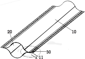
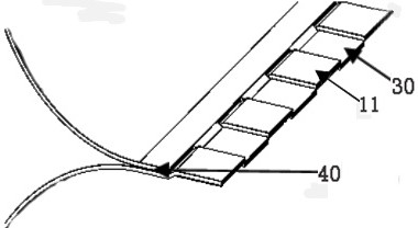
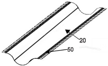
[0049] refer to Figure 1-Figure 4 , the present invention provides a pod-shaped elastic support bar device, comprising a pod upper lobe 10 and a pod lower lobe 20, both side edges of the pod upper lobe 10 and the pod lower lobe 20 include an adhesive surface 50 and a straight plane 60; Algorithms 11 arranged at intervals are successively arranged on the 60, and the alveoli 11 of the pod upper lobe 10 and the lower lobe 20 of the pod are intersected with each other, and a toughened fiber sheet 30 is arranged between adjacent alveoli 11, and the toughened Silica gel is coated on the type fiber sheet 30, the bonding surface 50, and the intersection 40 of the pod upper lobe 10 and the pod lower lobe 20, and the pod upper lobe 10 and the pod lower lobe 20 are bonded together by a flattening process through silica gel.

[0050] The alveoli 11 of the upper lobe 10 of the pod and the lower lobe 20 of the pod are intersected with each other. When the upper lobe 10 of the pod is bonded...

Embodiment 2

[0053] The present invention also provides a pod-shaped elastic support rod device, which differs from Embodiment 1 in that the device also includes specific holes (not shown in the figure) for preset elongated holes. The specific holes of the holes are located symmetrically on the straight sides of the upper 10 and lower 20 petals of the pod; strips of Velcro (not shown) are attached to the outer surface of the device.

[0054] It should be noted that the preset specific holes are for the subsequent use with other components in preparation for mutual use; the outer surface is attached with a strip of Velcro velcro, which can stick the overlapped club faces tightly after the device is wound up , capable of constraining the device from popping open.

[0055] Other content is identical with embodiment 1.


PUM


Abstract

The invention discloses a pod-shaped elastic supporting rod device which comprises an upper pod section and a lower pod section, and the edges of the two sides of the upper pod section and the edges of the two sides of the lower pod section each comprise a bonding face and a straight face; tooth grooves which are arranged at intervals are sequentially formed in the straight surface, the tooth grooves of the upper bean pod section and the tooth grooves of the upper bean pod section are arranged in a crossed mode, a toughening type fiber sheet is arranged between every two adjacent tooth grooves, high-toughness glue is coated on the toughening type fiber sheets and the bonding surface, and the upper bean pod section and the lower bean pod section are connected in a bonding mode through the high-toughness glue. The tooth grooves which are arranged at intervals are sequentially formed in the straight faces of the upper pod section and the lower pod section, the tooth grooves of the upper pod section and the tooth grooves of the lower pod section are arranged in a crossed mode, the toughening type fiber sheets are arranged between the adjacent tooth grooves, and the toughening type fiber sheets and the bonding faces are coated with the high-toughness glue. The upper bean pod section and the lower bean pod section are bonded together through the high-toughness glue, so that when the device is flattened or curled, cracking damage is not prone to being generated, and the breakage rate is reduced; and the bearing capacity and the yield are improved.

Description

technical field [0001] The invention belongs to the technical field of aerospace and aviation, and more specifically relates to a pod-shaped elastic support rod device. Background technique [0002] The spacecraft deployment technology is a key technology for large-scale space structures to achieve reliable deployment and shape retention in orbit, so as to have the ability to perform missions. With the development of large-scale, lightweight and high-precision space deployable structures, elastic deployable structures are more and more used in the deployment and support of aerospace structures. Typical applications are flexible solar cell arrays, solar sails, space Antennas, hoods, etc. The elastic expandable structure is an elastic energy storage type expandable structure. It relies on its own large-strain bending deformation and high-precision springback to realize the structure's collapse and expansion. It has the advantages of light weight, good rigidity, small storage ...

Claims


Application Information

Patent Timeline
Patent Type & Authority Applications(China)
IPC IPC(8): B64G1/22
CPCB64G1/222
Inventor 陈志平贾永清李福德安佰华柳坎
Owner CHINA ACAD OF AEROSPACE AERODYNAMICS
Why Eureka
Try Eureka