Anti-siphon backflow flushing valve
A flush valve, anti-siphon technology, applied in flush toilets, water supply devices, flushing equipment with water tanks, etc. The effect of siphoning backflow, reducing step cost, enhancing structural strength
- Summary
- Abstract
- Description
- Claims
- Application Information
AI Technical Summary
Problems solved by technology
Method used
Image

Examples
Embodiment 1
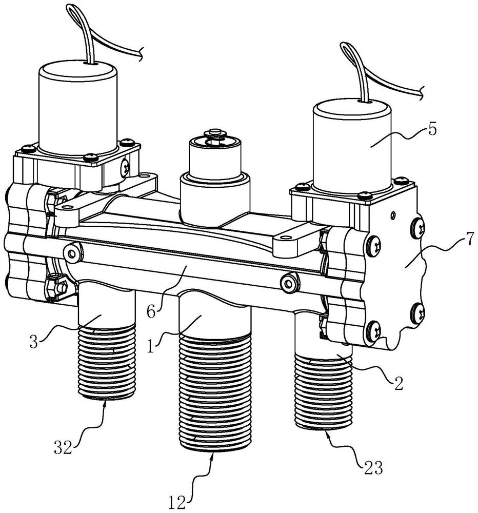
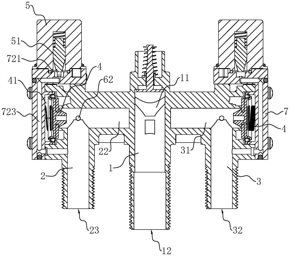
[0033] Embodiment one, with reference to figure 1 , figure 2 , The water inlet valve body 1 and the upper flush valve body 2 and the lower flush valve body 3 on both sides are injection molded as a whole. A conduction pipe 6 is connected between the upper flush valve body 2 and the lower flush valve body 3, and the conduction pipe 6 is integrally formed on one side of the water inlet valve body 1 and the two flush valve bodies by injection molding, and the upper flush water The cavity 22 and the lower flush water cavity 31 are directly connected by the conduction pipe 6, so that the upper flush water port and the lower flush water port of the toilet are connected to form a normally open flow channel, which has the effect of pressure relief and emptying.
[0034] The conduit 6 includes a long hole section 61 extending along the length direction of the water inlet chamber 11 , and a short hole section 62 connecting the long hole section 61 and the flushing chamber. The long h...
Embodiment 2
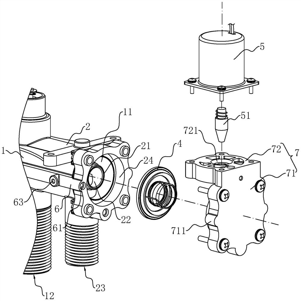
[0040] Embodiment two, refer to figure 2 , Figure 6 The difference between this embodiment and Embodiment 1 is that the water inlet valve body 1 and the upper flush valve body 2 and the lower flush valve body 3 on both sides can be integrally formed, or can be split and detachable by bolts and nuts. connected. The outer walls of the upper flush valve body 2 and the lower flush valve body 3 are provided with connecting holes 25 penetrating from the inner wall of the flushing chamber toward the outside, and the two ends of the conduction pipe 6 are respectively inserted into the two connecting holes 25, and then It is fixed by screw sleeves or other fasteners to facilitate disassembly and replacement.
Embodiment 3
[0041] Embodiment 3, the difference between this embodiment and Embodiment 2 is that the conduction tube 6 is a transparent tube made of transparent material, and the transparent conduction tube 6 is convenient for the user to observe the flow direction of the internal liquid and confirm that the upper flush water chamber 22 And whether it is emptied in the lower flush water chamber 31. However, in the scheme where the conduction pipe 6 is integrally formed with the valve body, the conduction pipe 6 can be integrally formed on the valve body through a two-color injection molding process.
[0042] The implementation principles of the three embodiments of the present application are as follows: when the toilet is flushed each time, the two electromagnetic valves 5 are all closed, because the upper flushing port of the toilet is connected to the outside air, and the position of the conduction pipe 6 is higher than that of the toilet tank. Therefore, the accumulated water in the u...
PUM
 Abstract
Description
Claims
Application Information
 - R&D
- Intellectual Property
- Life Sciences
- Materials
- Tech Scout
- Unparalleled Data Quality
- Higher Quality Content
- 60% Fewer Hallucinations
Browse by: Latest US Patents, China's latest patents, Technical Efficacy Thesaurus, Application Domain, Technology Topic, Popular Technical Reports.
© 2025 PatSnap. All rights reserved.Legal|Privacy policy|Modern Slavery Act Transparency Statement|Sitemap|About US| Contact US: help@patsnap.com