Refrigerator bottom plate polishing equipment

A refrigerator bottom plate and equipment technology, which is applied to grinding/polishing equipment, metal processing equipment, grinding machines, etc., can solve the problems of low production efficiency and achieve the effect of improving production efficiency and reducing labor intensity

Pending Publication Date: 2022-02-08
SUIYANG HUAFENG ELECTRICAL APPLIANCE
View PDF5 Cites 2 Cited by
  • Summary
  • Abstract
  • Description
  • Claims
  • Application Information

AI Technical Summary

Problems solved by technology

[0003] The present invention intends to provide a refrigerator floor grinding equipment to solve the problem in the prior art that when polishing the refrigerator floor, it is necessary to manually pick up the refrigerator floor to turn it over and put it in place, resulting in low production efficiency

Method used


Image

  • Refrigerator bottom plate polishing equipment
  • Refrigerator bottom plate polishing equipment
  • Refrigerator bottom plate polishing equipment

Examples


Embodiment 1

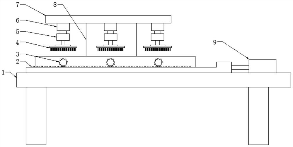
[0020] Embodiment 1, basically as attached figure 1 Shown: a refrigerator bottom plate grinding equipment, including an upper frame 7, a lower frame and three clamping mechanisms 10 arranged at intervals and used to fix the refrigerator bottom plate, the upper frame 7 is connected to the bottom frame of the lower frame through a support plate 8 Directly above. The lower frame includes two parallel support frames 1, and the upper frame 7 is connected with three grinding mechanisms through the longitudinally telescopic first cylinder 6. The grinding mechanism includes a motor 5 and a grinding head 4 positioned below the motor 5, and the motor 5 Connected with the telescopic end of the first air cylinder 6, the grinding head 4 is fixedly connected with the output shaft of the motor 5.

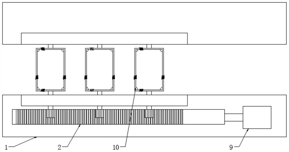
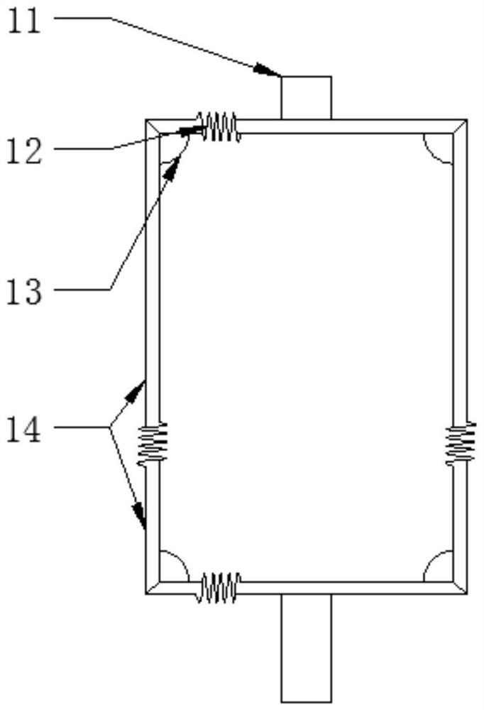
[0021] The grinding mechanism is located directly above the clamping mechanism 10 . combine figure 2 , image 3 As shown, the clamping mechanism 10 is formed by connecting end to end of four ...

Embodiment 2

[0022] Embodiment 2, the difference with embodiment 1 is as Figure 4 As shown: in the clamping mechanism 10 of this program, the two ends of the spring 12 are connected with screw rods 15, and the ends of the fixed-length rod 14 are provided with threaded holes, and the screw rod 15 is connected with the fixed-length rod 14 through the threaded holes.

Embodiment 3

[0023] The difference between Embodiment 3 and Embodiment 2 is that the power mechanism in this solution adopts another motor, and the output shaft of the motor is fixedly connected with the rotating shaft 11 .

[0024] Taking Embodiment 2 as an example, the specific implementation process is as follows: use the clamping mechanism 10 to clamp and fix the bottom plate of the refrigerator, and the grinding mechanism is located directly above the clamping mechanism 10, so the grinding mechanism can grind the surface of the refrigerator bottom plate when it is running. Because the clamping mechanism 10 is rotatably connected to the two support frames 1 through the rotating shaft 11, after finishing one side of grinding, the first cylinder 6 drives the grinding mechanism to move up, and the second cylinder 9 is activated to make the rack 2 slide, thereby driving the gear 3. Rotate, so that the clamping mechanism 10 turns over and the other side of the bottom plate of the refrigerato...


PUM


Abstract

The invention discloses refrigerator bottom plate polishing equipment in the technical field of refrigerator production equipment. The refrigerator bottom plate polishing equipment comprises an upper rack and a lower rack, wherein the upper rack is connected with a polishing mechanism through a longitudinally telescopic first air cylinder. The refrigerator bottom plate polishing equipment further comprises a clamping mechanism used for fixing a refrigerator bottom plate, and the two sides of the clamping mechanism are fixedly connected with rotating shafts; the lower rack comprises two supporting frames which are arranged in parallel, and the clamping mechanism is rotationally connected between the two supporting frames through the two rotating shafts; and the polishing mechanism is located over the clamping mechanism. According to the scheme, the refrigerator bottom plate does not need to be directly picked up to be turned over, the refrigerator bottom plate can be quickly turned over by rotating the clamping mechanism, and compared with the prior art, the labor intensity is reduced, and the efficiency is greatly improved.

Description

technical field [0001] The invention belongs to the technical field of refrigerator production equipment, and in particular relates to a refrigerator bottom plate grinding equipment. Background technique [0002] The bottom plate of the refrigerator is to rely on the press and the mold to exert external force on the plate to cause plastic deformation or separation, so as to obtain the stamping parts of the required shape and size. The bottom plate of the refrigerator has the characteristics of light and thin material, high strength and good rigidity. The bottom plate of the refrigerator produced in the prior art generally has burrs, and the parts with burrs will have various problems in the production of refrigerators, such as mismatching during assembly, slack between parts, etc., so the burrs should be cleaned. After grinding the burrs on one side of the refrigerator floor, the surface grinding device in the prior art needs to manually pick up the refrigerator floor and tu...

Claims


Application Information

Patent Timeline
Patent Type & Authority Applications(China)
IPC IPC(8): B24B9/00B24B41/06B24B41/00
CPCB24B9/00B24B41/06B24B41/00
Inventor 潘益军李显刚
Owner SUIYANG HUAFENG ELECTRICAL APPLIANCE
Why Eureka
Try Eureka