
Lathe for screw machining of screw rod pump

A technology of screw pumps and lathes, applied in metal processing equipment, grinding machines, manufacturing tools, etc., can solve the problem of high labor intensity and achieve the effect of reducing labor intensity

Inactive Publication Date: 2020-11-06
CHANGSHA HUHANG METALLURGICAL EQUIP FACTORY
View PDF12 Cites 2 Cited by
  • Summary
  • Abstract
  • Description
  • Claims
  • Application Information

AI Technical Summary

Problems solved by technology

[0002] After the screw of the screw pump is turned by a lathe, it needs to be manually polished. Since the surface area of ​​the screw of the screw pump is large, the labor intensity is high during manual grinding.

Method used


Image

  • Lathe for screw machining of screw rod pump
  • Lathe for screw machining of screw rod pump
  • Lathe for screw machining of screw rod pump

Examples


Embodiment Construction

[0039] The application will be described in further detail below in conjunction with the accompanying drawings.

[0040] The embodiment of the present application discloses a lathe for screw processing of a screw pump.

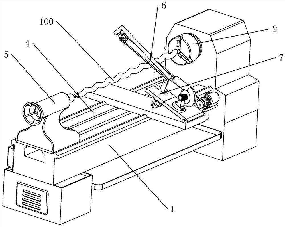
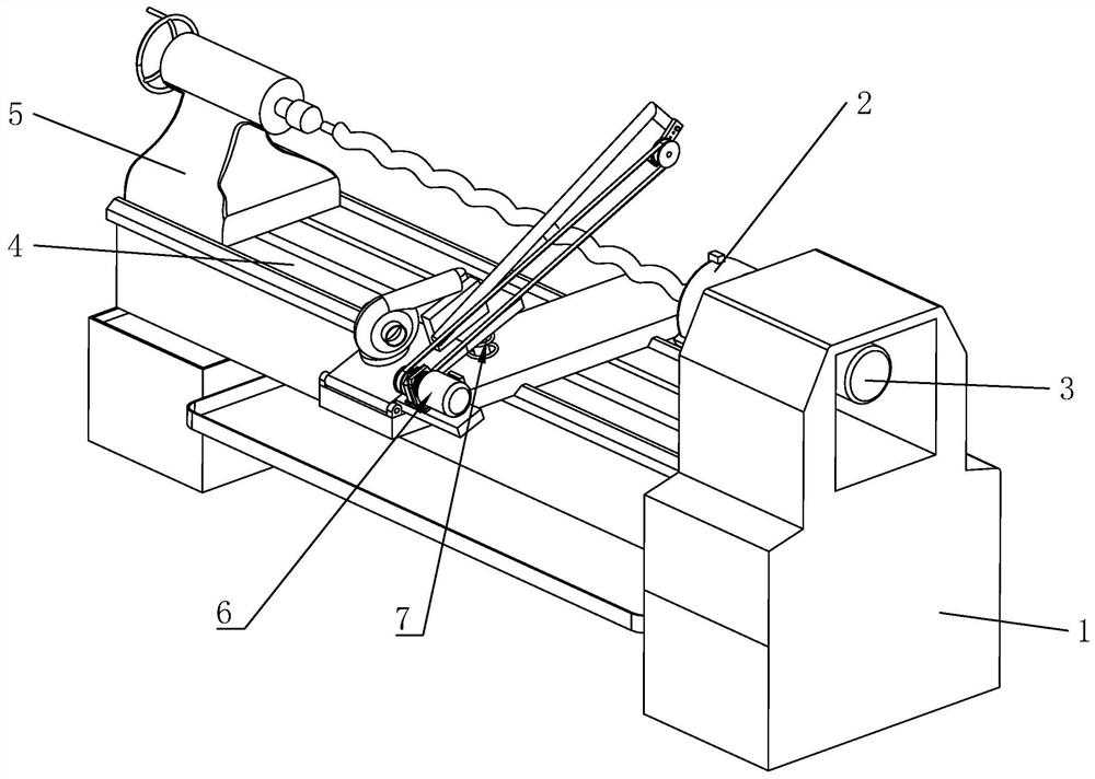
[0041] refer to figure 1 with figure 2 The lathe includes a lathe body 1, a three-jaw chuck 2 arranged on the lathe body 1, a first drive assembly 3 arranged on the lathe body 1 for driving the three-jaw chuck 2, and a guide rail arranged on the lathe body 1 4. The tailstock 5 arranged on the guide rail 4 and the grinding device 6 arranged on the lathe body 1 and slidingly connected with the guide rail 4 .

[0042] The worker clamps the screw rod 100 of the screw pump on the three-jaw chuck 2, and then adjusts the position of the tailstock 5 on the guide rail 4, so that the tailstock 5 presses the screw rod 100 on the three-jaw chuck 2, and then starts the second A drive assembly 3, the first drive assembly 3 drives the screw 100 to rotate through the thre...


PUM


Abstract

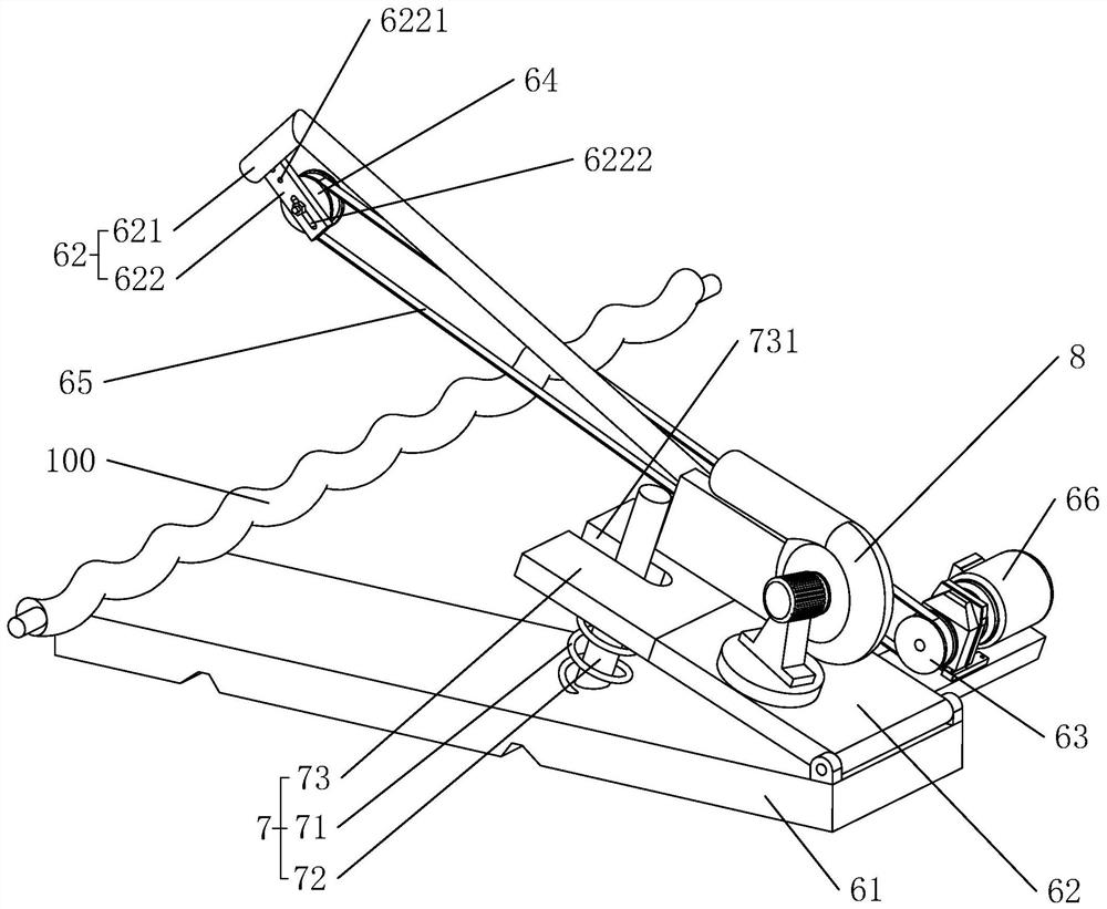
The invention relates to a lathe for screw machining of a screw rod pump, and relates to the field of screw processing of screw rod pumps. The lathe comprises a lathe body, a three-jaw chuck, a firstdrive component, a guide rail, a tailstock and a grinding device. The three-jaw chuck is arranged on the lathe body and used for clamping a screw. The first drive component is arranged on the lathe body and used for driving the three-jaw chuck to rotate. The guide rail is arranged on the lathe body. The tail bracket is arranged on the guide rail and used for jacking the screw. The grinding deviceis arranged on the lathe body. The grinding device comprises a base arranged on the lathe body, a bracket hinged on the base, a driving pulley rotationally connected with the bracket, a driven pulleyrotationally connected with the bracket, a grinding belt wound on the driving pulley and the driven pulley for grinding the screw, and a second driving component arranged on the bracket to drive the driving pulley to rotate. The grinding belt is pressed on the top of the screw. The lathe reduces the strength when the screw of the screw rod pump is manually ground.

Description

technical field [0001] The present application relates to the field of screw processing of screw pumps, in particular to a lathe for screw processing of screw pumps. Background technique [0002] After the screw of the screw pump is turned by a lathe, it needs to be manually polished. Since the surface area of ​​the screw of the screw pump is large, the labor intensity is high during manual grinding. Contents of the invention [0003] In order to reduce the strength of manually grinding the screw of the screw pump, the application provides a lathe for processing the screw of the screw pump. [0004] A kind of lathe for screw processing of screw pump provided by the application adopts the following technical scheme: [0005] A kind of lathe for processing the screw of a screw pump, comprising a lathe body, a three-jaw chuck arranged on the lathe body for clamping the screw rod, a first drive assembly arranged on the lathe body for driving the rotation of the three-jaw chuc...

Claims


Application Information

Patent Timeline
Patent Type & Authority Applications(China)
IPC IPC(8): B24B21/00B24B21/18B24B55/08B24B41/00B24B41/06B24B41/02
CPCB24B21/006B24B21/18B24B41/007B24B41/02B24B41/067B24B55/08
Inventor 姚茂
Owner CHANGSHA HUHANG METALLURGICAL EQUIP FACTORY
Learn More