Foaming method for thermal insulation layer of polyurethane foaming thermal insulation pipe

A polyurethane and thermal insulation pipe technology, which is applied in the foaming field of the thermal insulation layer of polyurethane foam thermal insulation pipes, can solve the problems of easy occurrence of voids in the thermal insulation layer and low operating efficiency, and achieve the effects of avoiding voids, uniform distribution, and good mixing effect

Pending Publication Date: 2022-02-08
SINOPEC SSC +1
View PDF1 Cites 2 Cited by
  • Summary
  • Abstract
  • Description
  • Claims
  • Application Information

AI Technical Summary

Problems solved by technology

[0005] The purpose of the present invention is to provide a method for foaming the insulation layer of polyurethane foam insulation pipes, which solves the problems of easy voids in the insulation layer and low operating efficiency when manufacturing polyurethane foam insulation pipes in the prior art

Method used


Image

  • Foaming method for thermal insulation layer of polyurethane foaming thermal insulation pipe
  • Foaming method for thermal insulation layer of polyurethane foaming thermal insulation pipe

Examples


Embodiment 1

[0039]The foaming method of the insulation layer of the polyurethane foam insulation pipe in this embodiment is used for foaming the insulation layer 73 of the polyurethane foam insulation pipe for heating in the oil field, between the inner pipe 72 and the outer pipe 71 of the polyurethane foam insulation pipe of the pipeline The intertube annulus is injected with foam material. In this embodiment, the outer diameter of the polyurethane foam insulation pipe is φ219 mm, and the material of the insulation layer 73 is polyisocyanate and combined polyether. The inner pipe 72 can be a steel pipe or an anti-corrosion pipe, and the outer pipe 71 is a polyethylene protective pipe.

[0040] The foaming method of the insulation layer of the polyurethane foam insulation pipe is as follows: figure 1 and figure 2 The foaming device for the insulation layer of the polyurethane foam insulation pipe shown, the foaming device for the insulation layer includes six subsystems, namely the mat...

Embodiment 2

[0059] The difference between this embodiment and Embodiment 1 is that in Embodiment 1, a transparent pipe section 37 is provided between the outlet of the injection pipe 32 and the gas injection joint 36 . In this embodiment, the injection pipe 32 is a whole pipe, which is directly connected to the gas injection joint 36 .

Embodiment 3

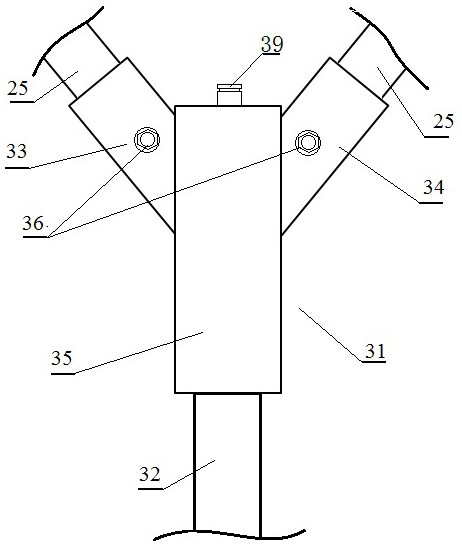
[0061] The difference between this embodiment and Embodiment 1 is that in Embodiment 1, the manifold joint 31 includes a first feed port 33 connected to the first feed pump 21, a feed port 33 connected to the second feed pump 22, The second feed end 34 and the discharge end 35 connected with the injection pipe 32 form a Y-shaped structure. In this embodiment, however, the first feed end 33 and the second feed end 34 are arranged in line, forming a T-shaped structure with the discharge end 35 .


PUM

PropertyMeasurementUnit
Outer diameteraaaaaaaaaa

Abstract

The invention belongs to the field of manufacturing of polyurethane foaming thermal insulation pipes, and particularly relates to a foaming method for a thermal insulation layer of a polyurethane foaming thermal insulation pipe. The foaming method for the heat preservation layer of the polyurethane foaming heat preservation pipe comprises the following steps that firstly, compressed gas is introduced into a material injection pipe, and the material injection pipe is used for injecting a foaming material into an inter-pipe annular space between an inner pipe body and an outer pipe body of the polyurethane foaming heat preservation pipe; 2, two foaming components needed by polyurethane foaming are pumped into the material injection pipe, and the foaming material is pushed into the inter-pipe annular space through compressed gas. The problems that in the prior art, when a polyurethane foaming heat preservation pipe is manufactured, a heat preservation layer is prone to cavities, and operation efficiency is low can be solved.

Description

technical field [0001] The invention belongs to the field of manufacturing polyurethane foam heat preservation pipes, in particular to a method for foaming the heat preservation layer of polyurethane foam heat preservation pipes. Background technique [0002] Since the birth of polyurethane synthetic materials in the 1930s, polyurethane foam insulation pipes have been rapidly developed as an excellent thermal insulation material, and its application range is becoming wider and wider. It is widely used in various pipelines such as heating, cooling, oil transportation, and gas transportation. Polyurethane rigid foam direct-buried insulation pipes have the characteristics of low cost compared with other types of pipes for transporting flowing media during use, and can also achieve low heat loss. Not only can energy saving be achieved, but also insulation is good. It has a long service life and can replace trench laying and overhead laying. Existing polyurethane foam insulatio...

Claims


Application Information

Patent Timeline
IPC IPC(8): B29C44/18B29C44/04B29C44/42B29C44/34B29L23/00
CPCB29C44/18B29C44/04B29C44/42B29C44/3442B29L2023/22
Inventor 李真陈自振郑道杰敬有超陈敬
Owner SINOPEC SSC
Why Eureka
Try Eureka