Aluminum pipe conveying mechanism for aluminum machining and construction method

A technology of conveying mechanism and construction method, which is applied in the direction of conveyor, manual conveying device, transportation and packaging, etc., which can solve the problems of time-consuming and laborious, increased construction cost, low construction efficiency, etc., and achieves convenient use, improved work efficiency and flexible use Effect

Pending Publication Date: 2022-02-08
河南中孚技术中心有限公司
View PDF21 Cites 0 Cited by
  • Summary
  • Abstract
  • Description
  • Claims
  • Application Information

AI Technical Summary

Problems solved by technology

[0002] During the construction of aluminum pipe processing plants, workers generally carry out follow-up operations on the pipes on the indoor construction platform. Due to the limited space in the factory building, the pipes are generally carried by manual movement; for aluminum pipes with larger diameters , workers can only carry one aluminum tube at a time, which is inefficient and time-consuming; if forklifts are used for transportation, because of the limited space in the workshop, forklifts may not be able to come in, and using forklifts for transportation increases construction costs

Method used


Image

  • Aluminum pipe conveying mechanism for aluminum machining and construction method
  • Aluminum pipe conveying mechanism for aluminum machining and construction method

Examples


Embodiment

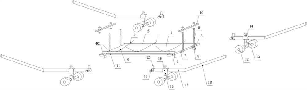
[0029] Example: see Figure 1-Figure 2 : An aluminum tube conveying mechanism for aluminum processing, comprising a support plate 1, legs 3 and ropes 6, the four corners of the bottom of the support plate 1 are provided with legs 3, and both sides of the support plate 1 are respectively provided with side baffles 2 , the side baffles 2 on each side are correspondingly provided with a positioning ring 5, and a rope 6 runs through between adjacent positioning rings 5; the two ends of the side of the support plate 1 are respectively provided with a connecting plate 4, and are connected A positioning hole 401 is dug on the plate 4, and a displacement assembly is arranged around the support plate 1, and is moved by the displacement assembly.

[0030] There are four connecting plates 4, two connecting plates 4 are respectively arranged at the two ends outside each side baffle plate 2, and connecting columns 11 are arranged between the two connecting plates 4 on each side, and the co...

Embodiment 2

[0038] Embodiment 2: The above-mentioned construction method of an aluminum tube conveying mechanism for aluminum processing specifically includes the following steps:

[0039] ①. Placement of pipelines:

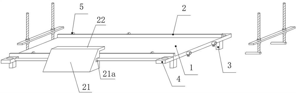
[0040] Place a guide plate 21 on both sides of the support plate 1, and set a rope on the positioning ring 5 between the two side baffles 2, and then pass the ends of the rope through the connecting column 11 and the side baffle respectively. In the space between, and press on the bottom of this side guide plate 21;

[0041] Use the guide plate 21 to move the pipes into the support plate 1 in sequence, and after the transfer is completed, put the guide plate 21 away, and tie the aluminum pipes with a rope;

[0042] ②, the installation of the limit device;

[0043] The inserting columns 9 are respectively inserted in the guide pipes at both ends of the support plate 1, and the horizontal plates 10 are sleeved on the two screw rods 8 at each end of the support plate 1, and t...


PUM


Abstract

The invention discloses an aluminum pipe conveying mechanism for aluminum machining and a construction method. The conveying mechanism comprises a supporting plate, supporting legs and a rope, the supporting legs are arranged under the supporting plate, side baffles are arranged at the two sides of the supporting plate, and connecting columns are arranged outside the side baffles. Guide plates are arranged outside the connecting columns, connecting plates are arranged at the four corners of the exterior of the supporting plate correspondingly, and jacking assemblies are arranged below the connecting plates. According to the present invention, aluminum pipes can be quickly conveyed in a workshop, the construction cost is reduced, and the working efficiency is improved; meanwhile, screws are arranged at the two ends of the supporting plate and are sleeved with the transverse plates, so that a limiting effect is achieved; during construction, the guide plates are arranged outside the supporting plate, so that the large-diameter aluminum pipe is convenient to carry, convenient to use, simple to operate and easy to popularize.

Description

Technical field: [0001] The invention relates to a pipe transportation device and a construction method, in particular to an aluminum pipe transportation mechanism for aluminum processing and a construction method. Background technique: [0002] During the construction of aluminum pipe processing plants, workers generally carry out follow-up operations on the pipes on the indoor construction platform. Due to the limited space in the factory building, the pipes are generally carried by manual movement; for aluminum pipes with larger diameters , Workers can only carry one aluminum tube at a time, which is inefficient and time-consuming; if a forklift is used for transportation, because the workshop space is limited, forklifts may not be able to come in, and the use of forklifts for transportation increases construction costs. Invention content: [0003] The technical problem to be solved by the present invention is: to overcome the deficiencies of the prior art, to provide a...

Claims


Application Information

Patent Timeline
Patent Type & Authority Applications(China)
IPC IPC(8): B65G7/12B65D25/10B65D81/05B65D85/20
CPCB65G7/12B65D25/102B65D81/05B65D85/20B65G2201/0217
Inventor 赵蕾吴慕天张涛锋康国强李伟伟李晓庆李伟杰张开兴
Owner 河南中孚技术中心有限公司
Why Eureka
Try Eureka