Continuous sucker rod operation assembly for oil well exploitation and exploitation technology

A sucker rod and oil well technology, used in the production of fluids, drill pipes, and earth-moving drilling, etc., can solve the problems of inability to install, increase costs, and can only be installed between two sucker rods, so as to avoid backflow, The effect of reducing leakage and reducing the time of use

Inactive Publication Date: 2022-02-08
姚瑶
View PDF0 Cites 0 Cited by
  • Summary
  • Abstract
  • Description
  • Claims
  • Application Information

AI Technical Summary

Problems solved by technology

Generally, after the oil well is drilled into the oil layer, the oil layer casing is lowered, and oil well cement is injected into the annular space between the casing and the well wall to maintain the well wall and seal the oil, gas, and water layers. The hole gun shoots through the oil layer to form a channel, which is lowered into the oil pipe, and the oil is raised from the bottom of the oil well to the head of the well with a suitable induction method. The sucker rod is a slender member of the pumping well. The oil pump plays the role of transmitting power. The length of a single sucker rod is 7.62m or 8m, 9.14m. The piston in the underground oil layer pumps oil through reciprocating motion. The current oil well length is generally about 2,000 meters, and the sucker rod is easy to rub against the oil well wall when it moves up and down in the oil well, so it needs to be pumped in two stages. A centralizer is installed between the oil rods to prevent the friction between the sucker rod and the wall of the oil well, but the existing centralizer can only be installed between two sucker rods, and cannot be installed at any position of the sucker rod, which is prone to wear and tear. In order to prevent the sucker rod from being worn out, the number of centralizers can only be increased, which increases the cost. For this reason, we provide a continuous sucker rod operation assembly and production process for oil well development

Method used


Image

  • Continuous sucker rod operation assembly for oil well exploitation and exploitation technology
  • Continuous sucker rod operation assembly for oil well exploitation and exploitation technology
  • Continuous sucker rod operation assembly for oil well exploitation and exploitation technology

Examples


Embodiment Construction

[0025] The following will clearly and completely describe the technical solutions in the embodiments of the present invention with reference to the accompanying drawings in the embodiments of the present invention. Obviously, the described embodiments are only some of the embodiments of the present invention, not all of them.

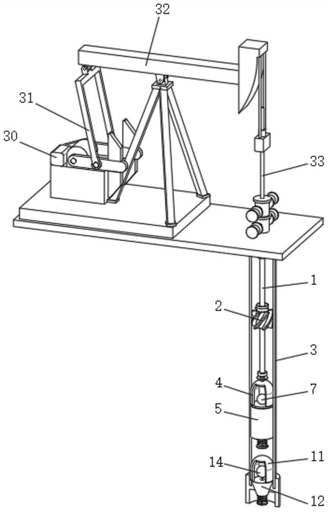
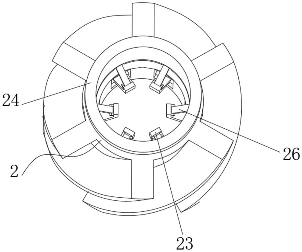
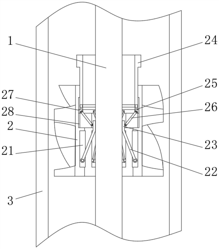
[0026] see figure 1 , figure 2 , image 3 , the present invention provides a technical solution: a continuous sucker rod operation assembly and mining process for oil well development, including a sucker rod 1, the outer movable sleeve of the sucker rod 1 is equipped with a centralizer 2, and the inner diameter of the centralizer 2 is larger than The diameter of the sucker rod 1 and the outer surface of the centralizer 2 are fixedly connected with a helical centralizer. By setting the centralizer 2, since the inner diameter of the centralizer 2 is larger than the diameter of the sucker rod 1, the centralizer 2 can be installed on the pumping rod. At ...


PUM


Abstract

The invention discloses a continuous sucker rod operation assembly for oil well exploitation and an exploitation technology, and relates to the technical field of oil fields, in particular to the continuous sucker rod operation assembly for oil well exploitation and the exploitation technology, which comprise a sucker rod, a centralizer is movably sleeved outside the sucker rod, the centralizer is internally and flexibly connected with a supporting rod. According to the continuous sucker rod operation assembly for oil well exploitation and the exploitation technology, a centralizer is arranged at any position of a sucker rod in a sleeving mode, then a threaded cylinder is rotated to push a movable ring to move downwards, then the movable ring pushes a pressing rod to move downwards, at the moment, the bottom end of the pressing rod presses a pressing block inwards, the pressing block is made to press the outer surface of the sucker rod, thus to fix the centralizer, and the centralizer can be conveniently fixed to any position of the surface of a sucker rod, so that the portion which is prone to abrasion is protected, the number of used centralizers is reduced, and cost is reduced.

Description

technical field [0001] The invention relates to the field of oil field technology, in particular to a continuous sucker rod operation assembly for oil well development and a production process. Background technique [0002] Oil wells are perforations drilled by drilling methods. Generally, after the oil well is drilled into the oil layer, the oil layer casing is lowered, and oil well cement is injected into the annular space between the casing and the well wall to maintain the well wall and seal the oil, gas, and water layers. The hole gun shoots through the oil layer to form a channel, which is lowered into the oil pipe, and the oil is raised from the bottom of the oil well to the head of the well with a suitable induction method. The sucker rod is a slender member of the pumping well. The oil pump plays the role of transmitting power. The length of a single sucker rod is 7.62m or 8m, 9.14m. The piston in the underground oil layer pumps oil through reciprocating motion. T...

Claims


Application Information

Patent Timeline
Patent Type & Authority Applications(China)
IPC IPC(8): E21B43/00E21B17/10E21B41/00
CPCE21B43/127E21B41/00E21B17/1078
Inventor 姚瑶李东海孙立平王采杨
Owner 姚瑶
Why Eureka
Try Eureka