
Concrete axis tension self-balancing test device and test method thereof

A test device and a technology for concrete specimens, which are used in measuring devices, using stable tension/compression testing materials, instruments, etc. The stress distribution of the specimen is complex and other problems, so as to achieve the effect of small structural mass, easy transportation and installation, and avoidance of eccentric force

Pending Publication Date: 2022-02-08
YANGZHOU UNIV
View PDF0 Cites 0 Cited by
  • Summary
  • Abstract
  • Description
  • Claims
  • Application Information

AI Technical Summary

Problems solved by technology

The external clamping type is generally prone to stress concentration at the clamping point. For inorganic brittle materials such as concrete, the fracture is likely to occur at the clamping point, and it is difficult to ensure that the fracture occurs at a uniform stress. The core is under tension, and the stress distribution in the specimen is also complicated
The paste type is relatively easy to ensure the axial tension, the stress distribution in the specimen is more uniform than the previous two methods, and the probability of fracture occurring in the uniform stress section is higher, but there is also the phenomenon of uneven stress distribution
It can be seen that the above methods all have their own defects, and none of them can well meet the requirements of the direct tensile test. The root cause of the above problems is that there will be different degrees of eccentricity in the process of the direct tensile test of the concrete material, which will lead to the failure of the tensile test. Inaccurate test data

Method used


Image

  • Concrete axis tension self-balancing test device and test method thereof
  • Concrete axis tension self-balancing test device and test method thereof
  • Concrete axis tension self-balancing test device and test method thereof

Examples


Embodiment Construction

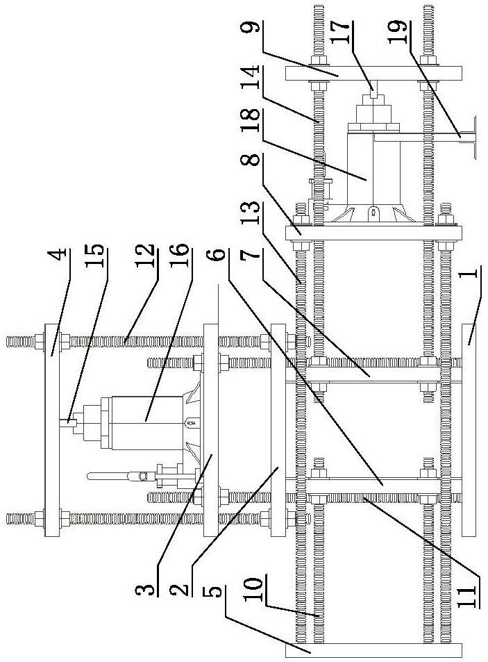
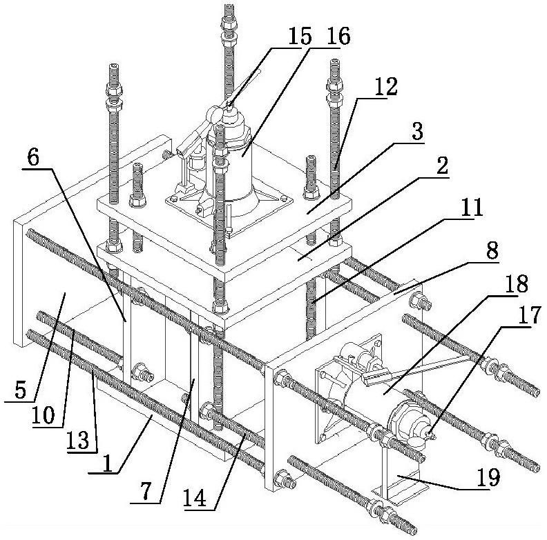
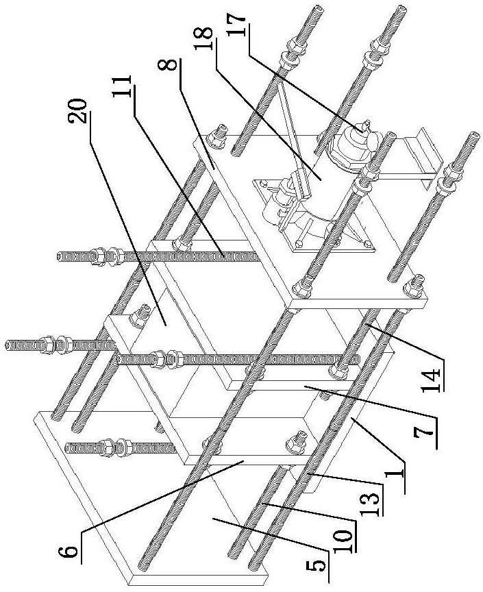
[0026] Such as Figure 1-3 As shown, it is a concrete axial tension self-balancing test device, which consists of a vertical tensile test mechanism and a horizontal tensile test mechanism.

[0027] Vertical tensile test mechanism: including reinforcement plate 1, reinforcement plate 2, reinforcement plate 3 and reinforcement plate 4, which are parallel to each other and centered on the same longitudinal axis, reinforcement plate 1, reinforcement plate 2, and reinforcement plate 3 3 and reinforcement plate four 4 are arranged sequentially from bottom to top; the four corners of reinforcement plate one 1 and reinforcement plate three 3 are respectively fixedly connected by four parallel first screw rods 11; the four corners of reinforcement plate two 2 and reinforcement plate four 4 Respectively fixedly connected through four second screw rods 12 arranged in parallel; the first screw rod 11 passes through the reinforcement plate two 2 with a gap, and the second screw rod 12 pass...


PUM


Abstract

The invention relates to a concrete axis tension self-balancing test device in the technical field of concrete tests. The concrete axis tension self-balancing test device comprises a vertical tension test mechanism and a horizontal tension test mechanism, the vertical tensile testing mechanism comprises a first reinforcing plate, a second reinforcing plate, a third reinforcing plate and a fourth reinforcing plate, pressure is converted into tensile force through a first jack, the horizontal tensile testing mechanism comprises a fifth reinforcing plate, a sixth reinforcing plate, a seventh reinforcing plate, an eighth reinforcing plate and a ninth reinforcing plate, and pressure is converted into tensile force through a second jack. During test, concrete test pieces are respectively adhered to the second reinforcing plate, the first reinforcing plate, the sixth reinforcing plate and the seventh reinforcing plate through epoxy resin glue. Stress is applied in two directions at the same time, so that the tensile strength of the concrete member under stress in two directions at the same time can be tested more accurately. The concrete test pieces can be self-balanced when being pulled, unbalance loading is not prone to occurring, and the test result is more accurate.

Description

technical field [0001] The invention belongs to the technical field of civil engineering concrete tests, in particular to a self-balancing test device for axial tension of concrete. Background technique [0002] The axial tensile strength of concrete is an important mechanical index. In the past, when determining the axial tensile strength of concrete, the main test methods can be divided into two categories: one is the direct test method, that is, the direct axial tensile test method; The second is the indirect test method, including the split test method and the bending and pulling test method. The splitting test is commonly used at home and abroad to test the axial tensile strength of concrete, but a large number of tests show that the splitting test method cannot truly reflect the axial tensile strength of concrete, and the splitting tensile strength is slightly greater than the direct tensile strength. In order to meet the test requirements and obtain a more accurate t...

Claims


Application Information

Patent Timeline
Patent Type & Authority Applications(China)
IPC IPC(8): G01N3/10G01N3/02
CPCG01N3/10G01N3/02G01N2203/0017G01N2203/0048
Inventor 刘雁邹新兴王安涟陈菁王昌远马洪伟宋兴禹
Owner YANGZHOU UNIV
Learn More