
Power generation equipment for generating power by using permanent magnet acceleration motor

A technology for power generation equipment and motors, which is applied in the direction of electric components, electrical components, electromechanical devices, etc., can solve the problems that the output shaft speed cannot be selected according to actual needs, the power cannot be distributed reasonably, and the power consumption of starting is large, etc., to achieve reasonable power , improve power generation capacity, and improve adaptability

Inactive Publication Date: 2022-02-08
肖双来
View PDF0 Cites 0 Cited by
  • Summary
  • Abstract
  • Description
  • Claims
  • Application Information

AI Technical Summary

Problems solved by technology

[0004] At present, large electric motors are used in large ships, large power plants or other large factories, but the current electric motor consumes a lot of power to start, and the use of output power after driving is poor, and the power cannot be distributed reasonably. And most motors can only output one output shaft after driving, and some manufacturers will also set two output shafts, but the speed of the two output shafts is the same or the speed has a fixed ratio, and the speed of the output shaft cannot be selected according to actual needs

Method used


Image

  • Power generation equipment for generating power by using permanent magnet acceleration motor
  • Power generation equipment for generating power by using permanent magnet acceleration motor
  • Power generation equipment for generating power by using permanent magnet acceleration motor

Examples


Embodiment Construction

[0027] In order to make the purpose, technical solution and advantages of the present invention clearer, the technical solution of the present invention will be described in detail below. Apparently, the described embodiments are only some of the embodiments of the present invention, but not all of them. Based on the embodiments of the present invention, all other implementations obtained by persons of ordinary skill in the art without making creative efforts fall within the protection scope of the present invention.

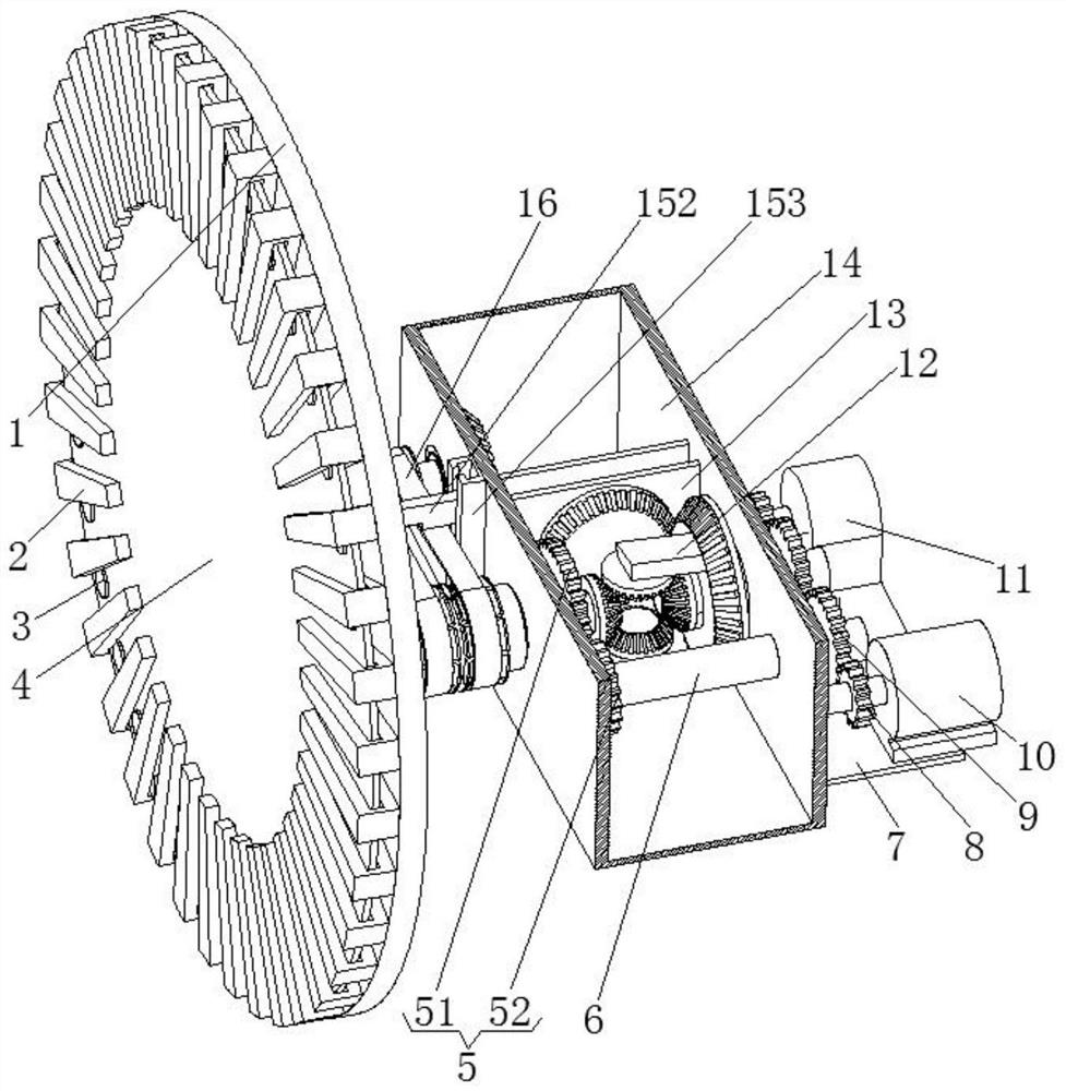
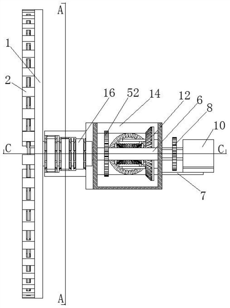
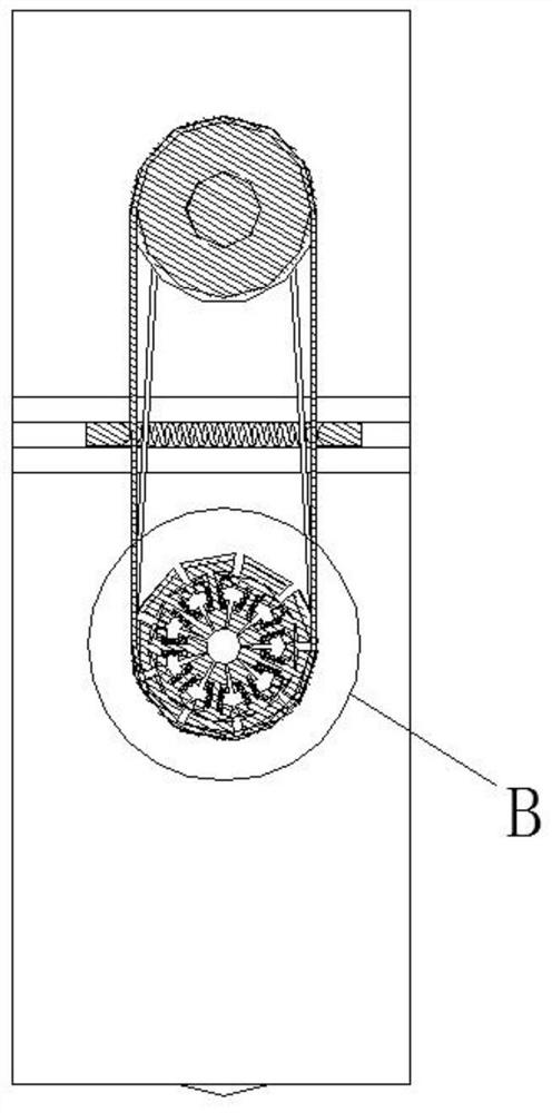
[0028] see Figure 1-Figure 7 As shown, the present invention provides a power generation device utilizing a permanent magnet acceleration motor to generate electricity, including a fixed chassis 1, an electromagnetic coil 2, a permanent magnet 3, an inner rotating disk 4, an outer casing 14, a first speed increasing assembly 21, a second speed increasing assembly The speed assembly 22 and the differential gear 12, the side circular array of the fixed chassis 1...


PUM


Abstract

The invention discloses power generation equipment for generating power by using a permanent magnet acceleration motor. The power generation equipment comprises a fixed base plate, electromagnetic coils, permanent magnets, an inner rotating disc, an outer shell, a first speed increasing assembly, a second speed increasing assembly and a differential mechanism, wherein the electromagnetic coils are fixed to the side face of the fixed base plate in a circular array mode, and an inner penetrating column rotationally penetrates through the center of the fixed base plate; and one end of the inner penetrating column is fixed to the center of the inner rotating disc. The power generation equipment has the advantages that the motor is started through small current, then the current is gradually increased, the power of the rotor is accumulated through the flywheel effect, and finally, the motor reaches the specified rotating speed; due to the fact that the current for starting the motor belongs to small current, consumed electric energy is small; the output rotating speed of the motor is increased through the gear set, and the input rotating speed of the motor is improved, so that the power generation capablity is improved; and in addition, different rotating speeds can be output in real time according to the type of the generator, so that the adaptability is improved, and power can be reasonably distributed.

Description

technical field [0001] The invention belongs to the field of power generation equipment, and in particular relates to a power generation device which utilizes a permanent magnet accelerating motor to generate power. Background technique [0002] A motor is a device that converts electrical energy into mechanical energy. It uses the energized coil (that is, the stator winding) to generate a rotating magnetic field and acts on the rotor (such as a squirrel-cage closed aluminum frame) to form a magnetoelectric force rotation torque. The motor is mainly composed of a stator and a rotor, and the energized wire moves under force in the magnetic field. The direction of the current is related to the direction of the current and the direction of the magnetic field (magnetic field direction). The working principle of the motor is that the magnetic field exerts force on the current to make the motor rotate. [0003] The differential is a mechanism that enables two drive shafts to rota...

Claims


Application Information

Patent Timeline
Patent Type & Authority Applications(China)
IPC IPC(8): H02K7/18H02K7/20H02K7/02H02K7/10H02K7/116
CPCH02K7/1807H02K7/02H02K7/116H02K7/20H02K7/1163H02K7/1004Y02E60/16
Inventor 肖双来
Owner 肖双来
Learn More