High-speed feeding transmission mechanism for ram type milling head for numerical control machine tool

A CNC machine tool and feed transmission technology, applied in the field of CNC machine tools, can solve the problems that the ram cannot be reciprocated very stably, the milling head generates extremely high temperature, and increases the production and processing costs, so as to ensure the adjustability and controllability , speed up, and save production and processing costs

Inactive Publication Date: 2019-12-17
杨伟朕
View PDF10 Cites 3 Cited by
  • Summary
  • Abstract
  • Description
  • Claims
  • Application Information

AI Technical Summary

Problems solved by technology

[0004] The high-speed feed transmission mechanism of the ram-type milling head used in the CNC machine tool in the prior art still has certain deficiencies, the ram cannot reciprocate very stably; and the milling head is working because the milling cutter is constantly cutting The workpiece, so the milling head will generate extremely high temperature. In the prior art, the milling head is generally sprayed with cooling liquid through a separate water cooling mechanism to reduce its temperature. This cooling method requires a separate power mechanism, not only Increased production and processing costs, and the separate water-cooling mechanism cannot synchronize with the ram, which will easily lead to untimely cooling, resulting in deformation of the milling head due to excessive temperature

Method used


Image

  • High-speed feeding transmission mechanism for ram type milling head for numerical control machine tool
  • High-speed feeding transmission mechanism for ram type milling head for numerical control machine tool
  • High-speed feeding transmission mechanism for ram type milling head for numerical control machine tool

Examples


Embodiment Construction

[0026] The following will clearly and completely describe the technical solutions in the embodiments of the present invention with reference to the accompanying drawings in the embodiments of the present invention. Obviously, the described embodiments are only some, not all, embodiments of the present invention.

[0027] In describing the present invention, it should be understood that the terms "upper", "lower", "front", "rear", "left", "right", "top", "bottom", "inner", " The orientation or positional relationship indicated by "outside", etc. is based on the orientation or positional relationship shown in the drawings, and is only for the convenience of describing the present invention and simplifying the description, rather than indicating or implying that the referred device or element must have a specific orientation, so as to Specific orientation configurations and operations, therefore, are not to be construed as limitations on the invention.

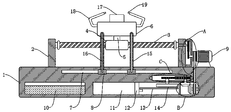
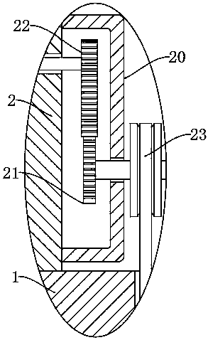
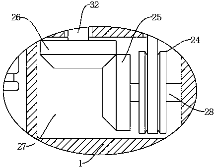
[0028] refer to Figure ...


PUM


Abstract

The invention discloses a high-speed feeding transmission mechanism for a ram type milling head for a numerical control machine tool. A base is included. The two sides of the side wall of the base arefixedly connected with stand columns. The opposite side walls of the stand columns are rotationally connected with a reciprocating lead screw, and the reciprocating lead screw is in threaded connection with a screw nut. The side wall of the screw nut is fixedly connected with a ram through a connecting rod, and the side wall of the ram is fixedly connected with the milling head. Through the arrangement of a first drive mechanism, a liquid pumping mechanism, a pushing mechanism, a first transmission mechanism, a second transmission mechanism and a second drive mechanism, a motor can be used for driving the reciprocating lead screw to rotate so that the ram feeding motion can be finished, and compared with a traditional feeding mechanism, more stability is achieved; meanwhile, the motor further synchronously drives a sliding plug to reciprocate, accordingly, cooling liquid is sprayed to the surfaces of the milling head and a milling tool, the milling head cooling and temperature reduction function is achieved, the producing and machining cost is saved, meanwhile, synchronous actions with the ram can be conducted, and deformation caused by the tool high milling head temperature due to untimely cooling is avoided.

Description

technical field [0001] The invention relates to the technical field of numerical control machine tools, in particular to a high-speed feed transmission mechanism of a ram type milling head for a numerical control machine tool. Background technique [0002] With the continuous development of society and technology, CNC machine tools have become an indispensable production unit in modern mechanical processing. CNC machine tools can better solve complex, precise, small-batch, and multi-variety parts processing problems. , High-efficiency automatic machine tools represent the development direction of modern machine tool control technology and are a typical mechatronic product. [0003] The milling head is installed on the milling machine and connected with the main shaft to drive the milling cutter to rotate. It is the main component of the machine tool equipment. The high-speed feed transmission mechanism of the milling head can make the ram move quickly to complete the feed w...

Claims


Application Information

Patent Timeline
Patent Type & Authority Applications(China)
IPC IPC(8): B23C9/00B23Q5/28B23Q5/40B23Q5/48B23Q11/10
CPCB23C9/00B23C9/005B23Q5/28B23Q5/40B23Q5/48B23Q11/10
Inventor 杨伟朕
Owner 杨伟朕
Why Eureka
Try Eureka