
Method for continuously outputting high power on basis of few-gear speed change mechanism for vehicle

A technology of speed change mechanism and high power, applied in vehicle components, transportation and packaging, control devices, etc., can solve the problems of increased machinery manufacturing cost, increased vehicle weight, complex mechanical structure, etc., and achieve the effect of improving torque output

Active Publication Date: 2014-05-14
DONGFENG MOTOR CORP HUBEI
View PDF5 Cites 3 Cited by
  • Summary
  • Abstract
  • Description
  • Claims
  • Application Information

AI Technical Summary

Problems solved by technology

However, multi-gear also brings disadvantages such as complex mechanical structure, increased vehicle weight, and increased mechanical manufacturing costs.

Method used


Image

  • Method for continuously outputting high power on basis of few-gear speed change mechanism for vehicle
  • Method for continuously outputting high power on basis of few-gear speed change mechanism for vehicle
  • Method for continuously outputting high power on basis of few-gear speed change mechanism for vehicle

Examples


Embodiment Construction

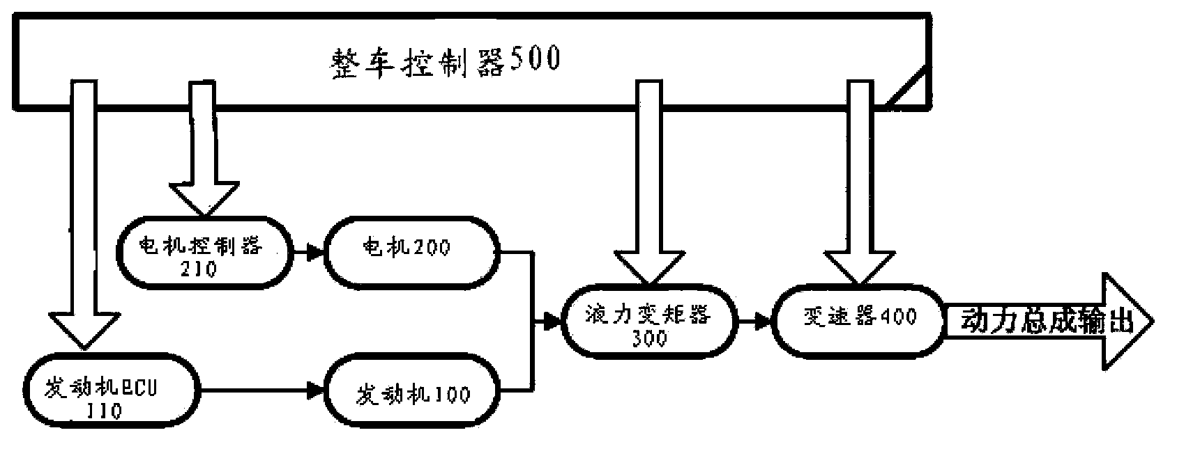
[0024] Such as figure 1 Shown, the power assembly of the present invention method comprises that internal combustion engine is referred to as motor 100 below, motor 200; 400 is the speed changer 400 of manual transmission, only uses the mechanical speed changer of a forward gear and a reverse gear.

[0025] The engine controller ECU110 is used to control the output of the engine, the motor controller 210 is used to control the output of the motor, and the vehicle controller 500 is used to control the engine controller ECU110, the motor controller 210, the torque converter 300 and the transmission 400 respectively .

[0026] The control method of the above structure in the vehicle running process is: that is, the method of the present invention is that when the vehicle starts, the engine speed rises rapidly from 0 to idle speed according to the requirements of the control system with the opening of the throttle valve. After the vehicle is started, the motor speed is synchroniz...


PUM


Abstract

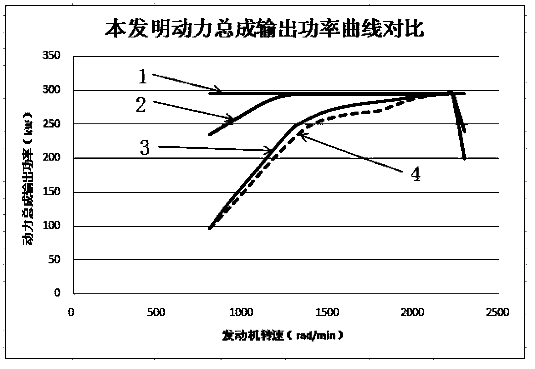
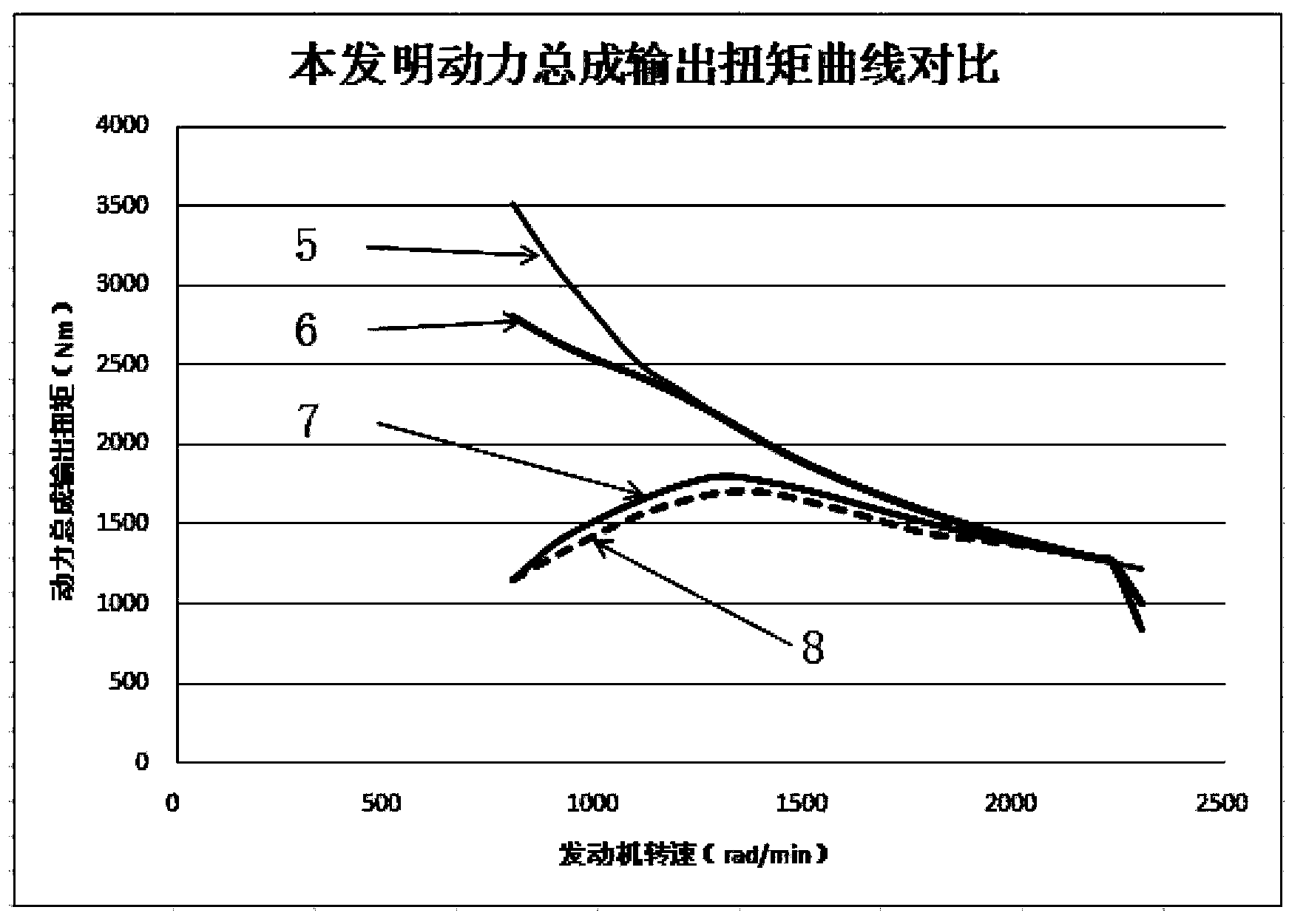
The invention discloses a method for continuously outputting high power on the basis of a few-gear speed change mechanism for a vehicle. The method is characterized in that power and transmission matching output of a power assembly includes two stages, a rotational speed of an output end of the speed change mechanism at the first stage is changed from zero to a set rotational speed, an internal combustion engine and a second power unit simultaneously output power to a hydraulic torque converter, and a transmission ratio of the hydraulic torque converter is changed; after the rotational speed of the output end of the speed change mechanism at the second stage exceeds the set rotational speed, the internal combustion engine and / or the second power unit output power to the hydraulic torque converter, the transmission ratio of the hydraulic torque converter is unchanged, an input rotational speed of the speed change mechanism is equal to an output rotational speed of a hydraulic torque converter end, and an output rotational speed of the speed change mechanism is equal to a quotient obtained after an input rotational speed of a speed changer is divided by a transmission ratio of the speed change mechanism. The method has the advantages that power and torque curves of a matched power system of the vehicle are close to characteristic curves of an equivalent-power engine with engine characteristics of a perfect power system of the vehicle under the condition that the vehicle has few gears or even only a single gear, accordingly, the dynamic property of the vehicle can be improved, and the economical efficiency of the vehicle can be enhanced.

Description

technical field [0001] The invention belongs to the power output control technology of an automobile power system, and in particular relates to a method for realizing continuous high-power output of a vehicle under the condition of a few-gear transmission mechanism. Background technique [0002] At present, the engine commonly used in automobiles is a piston internal combustion engine. Its relatively ideal equal-power engine has obvious defects such as low reserve power in the low-speed area and insufficient driving force. This defect causes the power curve of the vehicle to deviate from the ideal. The power curve of the engine vehicle, so that the power of the whole vehicle is not strong, and the economy is not good. In order to overcome the defect of the piston internal combustion engine, make the power curve of the vehicle equipped with the piston internal combustion engine closer to the ideal power curve, and at the same time ensure the power and economy of the car, the ...

Claims


Application Information

Patent Timeline
IPC IPC(8): B60K17/28
Inventor 黄松寇西征林光成李进伟叶建伟杨国超刘波汪振晓杨诚祝挺吴齐芳宋杰
Owner DONGFENG MOTOR CORP HUBEI
Learn More