Femoral fracture traction reduction device
A technique for traction reduction and femoral fracture, which is applied in medical science, external fixator, surgery, etc. It can solve the problems of poor flexibility in multi-angle adjustment and inability to realize adjustment and movement, and achieve the effect of intuitive adjustment method and simplified structure.
- Summary
- Abstract
- Description
- Claims
- Application Information
AI Technical Summary
Problems solved by technology
Method used
Image
Examples
Embodiment 1
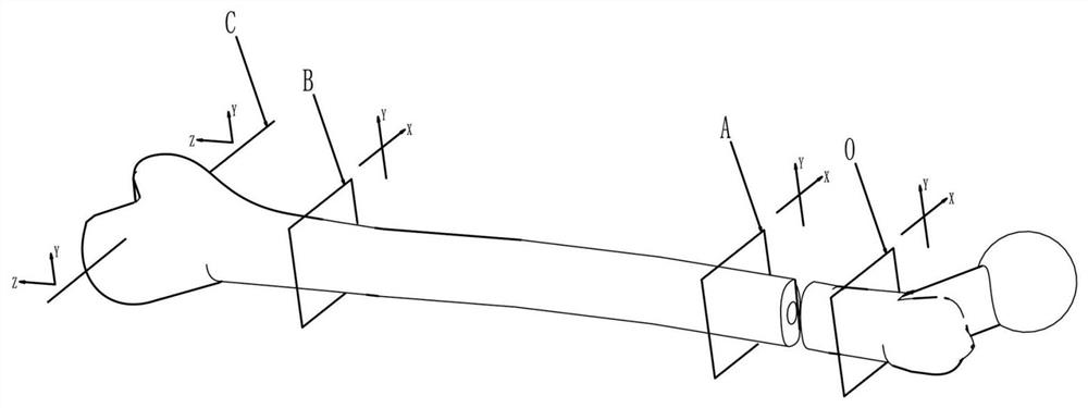
[0043] Embodiment 1: A femoral fracture traction and reduction device, used for traction and adjustment of the two femoral segments before and after the fracture, such as figure 1 A simplified schematic diagram is shown, and it can be seen that the device should include a rear two-dimensional adjustment unit O, a proximal two-dimensional adjustment unit A, a distal two-dimensional adjustment unit B and a front traction unit C. In view of the dislocation of any degree of freedom in the two segments of the femur that is in fracture, the device mainly realizes the multi-angle adjustment function for the other bone segment by fixing one bone segment and adjusting the other bone segment. The proximal two-dimensional adjustment unit A and the distal two-dimensional adjustment unit B are used for angular adjustment, and the front traction unit C is used for traction and steering. Compared with the existing traction reset device, the structure of this scheme is simplified, the adjustm...
Embodiment 2
[0064] Embodiment 2: On the basis of Embodiment 1, some modifications are made to the front traction unit C, such as Image 6 As shown, the L-shaped bar includes a vertical bar 16 and a cross bar 17, and two horizontal sliding sleeves 24 are set on the cross bar 17, and the lower end of each horizontal sliding sleeve 24 is vertically fixed with a fixed column 25, and the end of each fixed column 25 Each part is respectively connected with push-pull rods 20, and the front end of each push-pull rod 20 is respectively connected with two ends of the penetrating rod 22.
[0065] The main body of the bed hook 3 is provided with a vertically penetrating perforation, and the column 16 is matched and fitted in the perforation, and the side of the perforation is provided with a lock wire. As can be seen in the figure, the lifting adjustment mode of the fixed columns 25 on both sides is to rely on vertical sliding and fixing between the bed hook 3 and the column 16 .
Embodiment 3
[0066] Embodiment 3: On the basis of Embodiment 1, this embodiment mainly designs that there is a restraint structure between the lower beam 12 and the corresponding horizontal sliding sleeve 11 to prevent rotation. like Figure 7 The two parallel vertical rods and two parallel horizontal rods of the clamping parts shown in the figure, each rod is provided with a milling plane 7 on the side, and there is a matching arch plane in the corresponding sliding sleeve, and the milling plane cooperates with the arch plane, so that When the rod member slides with the corresponding sliding sleeve, it can only slide axially but not rotate. Therefore, the clamping part can withstand the pressure from the front or rear direction without rolling over.
PUM
 Abstract
Description
Claims
Application Information
 - R&D
- Intellectual Property
- Life Sciences
- Materials
- Tech Scout
- Unparalleled Data Quality
- Higher Quality Content
- 60% Fewer Hallucinations
Browse by: Latest US Patents, China's latest patents, Technical Efficacy Thesaurus, Application Domain, Technology Topic, Popular Technical Reports.
© 2025 PatSnap. All rights reserved.Legal|Privacy policy|Modern Slavery Act Transparency Statement|Sitemap|About US| Contact US: help@patsnap.com


