Cleaning and sterilizing equipment for uterine curettage device in obstetrics and gynecology department
A technology for sterilization equipment and curettage, which is applied to the field of cleaning and sterilizing equipment for curettage in obstetrics and gynecology, can solve problems such as low efficiency, high labor intensity, and small quantity, so as to reduce labor intensity, avoid conflicts, wash and sterilize Easy to transfer effects
- Summary
- Abstract
- Description
- Claims
- Application Information
AI Technical Summary
Problems solved by technology
Method used
Image
Examples
Embodiment 1
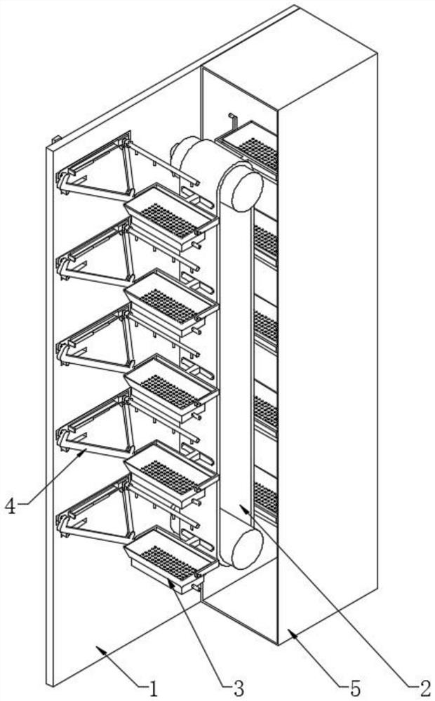
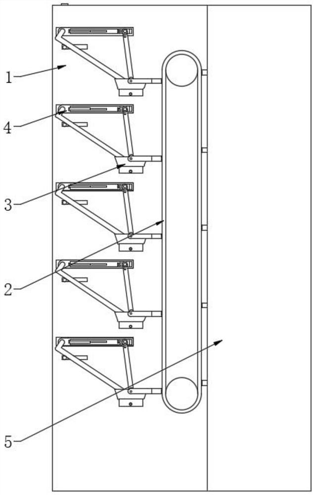
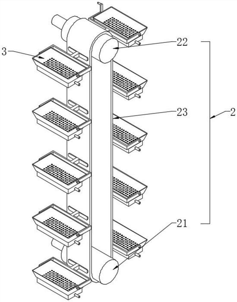
[0031] see Figure 1-6, a device for cleaning and sterilizing obstetrics and gynecology curettage devices, including a supporting vertical plate 1, a belt conveyor 2, a tray 3, a cleaning part 4 and a sterilization cover 5, and the supporting vertical plate 1 is used to support other components on the device Components, the tray 3 is used to place the curettage appliance, the belt conveyor 2 is used to transfer the tray, the cleaning part 4 is used to wash and clean the uterine curettage appliance, and the sterilization cover 5 is used to sterilize the cleaned appliance, and the sterilization cover 5 can Ultraviolet germicidal lamps are set; the belt conveyor 2 is arranged on one side of the bearing vertical plate 1 and is vertically distributed, and the belt conveyor 2 is provided with a driving belt roller 21, a passive belt roller 22 and a connecting driving belt roller 21 and a passive belt roller 22 The driving belt 23, the driving belt roller 21 and the passive belt roll...
Embodiment 2
[0033] see Figure 4 The difference from Embodiment 1 is that the bottom of the tray 3 is fixedly provided with a water storage bottom case 33 located at the bottom of the water leakage hole 31, and the end of the water storage bottom case 33 away from the bearing vertical plate 1 is fixedly provided with a drain pipe 331, and the waste water after washing Will pass through the leak hole 31 and enter the water storage bottom shell 33, when the transmission belt 23 is in the process of running, the waste water in the water storage bottom shell 33 will always be thrown outside through the drain pipe 331, and will not pollute each other.
Embodiment 3
[0035] see Figure 5 with Figure 7 , and the difference from Embodiment 1 is that a push valve 422 is connected in series on the water spray pipe 42. The push valve 422 is a common water valve, and a push switch is arranged on it to connect one end of the water spray pipe 42 to an external water supply pipeline. By controlling the pressing valve 422, the pressing valve 422 can be turned on and off. A positioning plate 411 is fixedly arranged on the side of the positioning guide plate 41 close to the collision rod 431. One side of the positioning plate 411 is fixedly connected to one end and used in conjunction with the pressing valve 422. When the water spray pipe 42 moves towards the direction of the elastic telescopic rod 4111, one end of the elastic telescopic rod 4111 will touch the push switch of the push valve 422, and the water spray pipe 42 is closed at this time, and it has the function of automatically stopping the water. Efficacy, with water-saving function, furth...
PUM
 Abstract
Description
Claims
Application Information
 - R&D
- Intellectual Property
- Life Sciences
- Materials
- Tech Scout
- Unparalleled Data Quality
- Higher Quality Content
- 60% Fewer Hallucinations
Browse by: Latest US Patents, China's latest patents, Technical Efficacy Thesaurus, Application Domain, Technology Topic, Popular Technical Reports.
© 2025 PatSnap. All rights reserved.Legal|Privacy policy|Modern Slavery Act Transparency Statement|Sitemap|About US| Contact US: help@patsnap.com


