
Automatic discharging mechanism

A technology of automatic discharge and chassis, applied in the field of mechanical processing equipment, can solve the problems of heavy manual operation workload, strong manual dependence, low degree of automation, etc., and achieve the effect of high processing efficiency, simple control and high degree of automation

Pending Publication Date: 2022-02-11
VICHNET COMM SCI & TECH
View PDF1 Cites 0 Cited by
  • Summary
  • Abstract
  • Description
  • Claims
  • Application Information

AI Technical Summary

Problems solved by technology

[0004] However, the above-mentioned automatic welding equipment still has the following defects in the actual use process: 1. It is necessary to manually make transverse ribs and longitudinal ribs, that is, manually transport the coiled steel wires to the straightening station for straightening, and then cut them Steel wires of suitable length to produce transverse and longitudinal ribs of appropriate length; 2. It is necessary to manually arrange the prepared transverse ribs on the first feeding mechanism at equal intervals; 3. It is necessary to manually arrange the prepared longitudinal ribs Added to the feeding station on the second feeding mechanism; 4. The whole process relies heavily on labor, the degree of automation is low, the workload of manual operation is large, and the work efficiency is low

Method used


Image

  • Automatic discharging mechanism
  • Automatic discharging mechanism
  • Automatic discharging mechanism

Examples


Embodiment Construction

[0047] Hereinafter, the present application will be further described in conjunction with specific implementation methods. It should be noted that, on the premise of not conflicting, the various embodiments or technical features described below can be combined arbitrarily to form new embodiments.

[0048] In the description of this application, it should be noted that for orientation words, such as the terms "center", "horizontal", "longitudinal", "length", "width", "thickness", "upper", "lower" , "Front", "Back", "Left", "Right", "Vertical", "Horizontal", "Top", "Bottom", "Inner", "Outer", "Clockwise", "Counterclockwise ” and other indication orientations and positional relationships are based on the orientations or positional relationships shown in the drawings, which are only for the convenience of describing the application and simplifying the description, rather than indicating or implying that the device or element referred to must have a specific orientation, use a speci...


PUM


Abstract

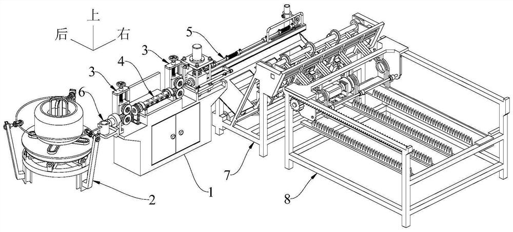
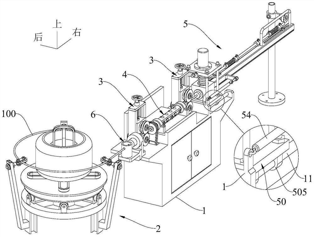
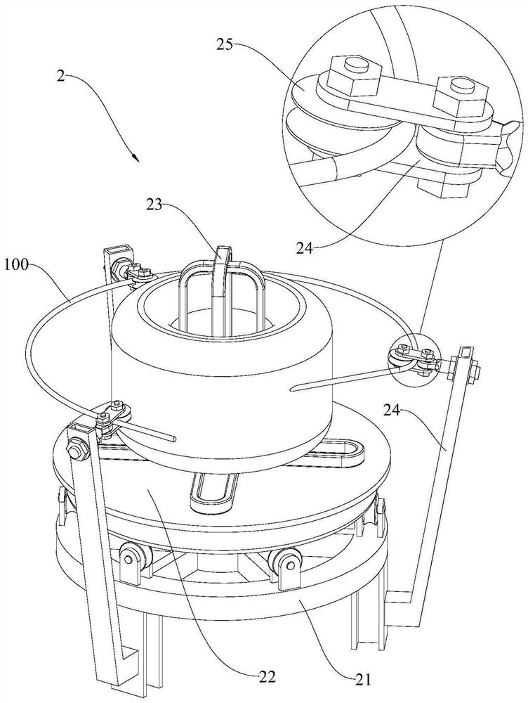
An automatic discharging mechanism comprises a machine box, a fixing assembly, a traction assembly, a straightening assembly, a cutting assembly, a feeding assembly and a discharging assembly. The fixing assembly and the cutting assembly are arranged on the left side and the right side of the machine box respectively, the traction assembly and the straightening assembly are arranged on the machine box, and the feeding assembly is arranged on the front side or the rear side of the cutting assembly. The discharging assembly comprises a mounting frame, a discharging piece and a feeding piece. The mounting frame is arranged on the side, away from the cutting assembly, of the feeding assembly, a plurality of positioning grooves are formed in the mounting frame in the front-back direction at intervals, and the discharging piece and the feeding piece are arranged on the mounting frame. The traction assembly sequentially pulls the starting end of a steel wire on the fixing assembly to the straightening assembly and the cutting assembly for be straightening and cutting. The feeding assembly automatically conveys the cut-off steel wires to the discharging piece. The discharging piece conveys the steel wires into the positioning grooves, and the feeding piece pushes the steel wires in the positioning grooves to move leftwards or rightwards. The automatic discharging mechanism is easy and convenient to operate and control, high in automation degree, high in machining efficiency and beneficial to industrial production.

Description

technical field [0001] The application relates to the technical field of mechanical processing equipment, in particular to an automatic discharge mechanism. Background technique [0002] At present, when processing grid bridges with a "匚"-shaped structure, it is necessary to manually arrange the transverse ribs and longitudinal ribs at equal intervals to form a grid structure, and then use a welding machine to weld at the junction of the transverse ribs and longitudinal ribs to obtain The steel wire skeleton with a grid structure, and finally the steel wire skeleton with a grid structure is bent to form a "匚"-shaped structure. [0003] In the prior art, in order to weld the transverse ribs and longitudinal ribs into a steel wire skeleton, the patent document with the publication number CN112935156A discloses an automatic welding equipment, including a frame, a welding mechanism, a first feeding mechanism, and a second feeding mechanism , traction mechanism, automatic unload...

Claims


Application Information

Patent Timeline
IPC IPC(8): B21F15/08B21F1/02B21F11/00B21F23/00
CPCB21F15/08B21F1/026B21F11/00B21F23/00Y02P70/10
Inventor 应露瑶吴伟国李瑞志
Owner VICHNET COMM SCI & TECH
Learn More