
Support fixing jig

A technology for bracket fixing and jigs, which is applied in the direction of manufacturing tools, auxiliary devices, auxiliary welding equipment, etc., can solve the problems of low jig efficiency and achieve the effects of improving work efficiency, convenient disassembly, and small space occupation

Pending Publication Date: 2022-02-11
苏州谷恩精密机械有限公司
View PDF0 Cites 0 Cited by
  • Summary
  • Abstract
  • Description
  • Claims
  • Application Information

AI Technical Summary

Problems solved by technology

[0004] The purpose of the present invention is to provide a bracket fixing jig, which solves the technical problem of low efficiency of the existing jig for welding

Method used


Image

  • Support fixing jig
  • Support fixing jig
  • Support fixing jig

Examples


Embodiment Construction

[0038] The following will clearly and completely describe the technical solutions in the embodiments of the present invention with reference to the accompanying drawings in the embodiments of the present invention. Obviously, the described embodiments are only some, not all, embodiments of the present invention. The following description of at least one exemplary embodiment is merely illustrative in nature and in no way taken as limiting the invention, its application or uses.

[0039] To keep the following description of the embodiments of the present invention clear and concise, detailed descriptions of known functions and known components are omitted from the present invention.

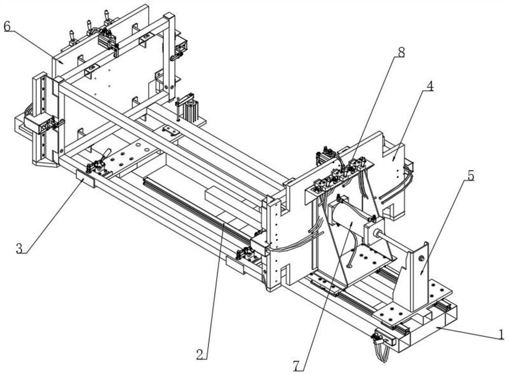
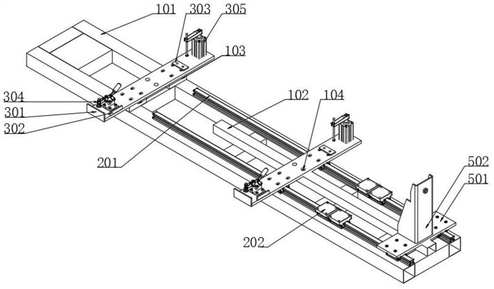
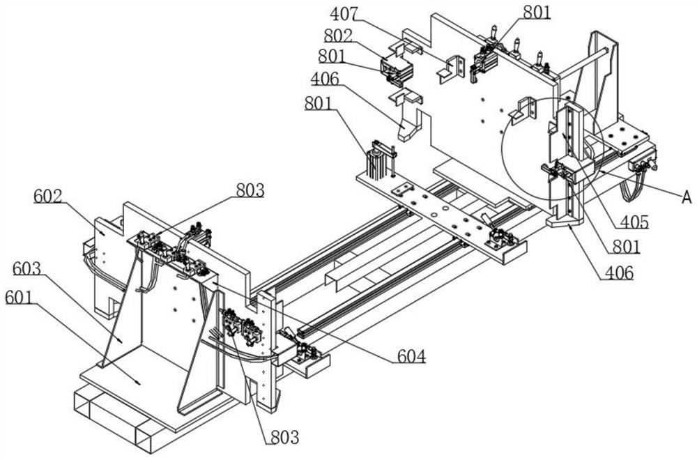
[0040] see Figure 1-16 As shown, in this embodiment, a bracket fixing fixture is provided, including: a welding work frame 1, a slide rail group 2 is installed on the upper side of the welding work frame 1, and two rails are installed on the upper side of the welding work frame 1 The plate 3 and ...


PUM


Abstract

The invention discloses a support fixing jig, and relates to the technical field of welding. The support fixing jig comprises a welding work frame, a sliding rail set is arranged on the upper side of the welding work frame, two rail plates are arranged above the welding work frame, and a movable side is arranged on the upper side of the sliding rail set in a sliding fit mode. The movable side and the fixed side are arranged above the welding work frame, the movable side and the fixed side are used for positioning and fixing support spare parts, all welding seams and welding spots can be effectively avoided, welding work can be conveniently carried out, and the overall work efficiency is improved. The support fixing jig is arranged on the welding work frame in a vertical mode, the whole occupied space is small, the support fixing jig can be retreated to the two sides of the welding work frame when being not used, the middle space and the sliding rail set are reserved for other welding operation, and the whole support fixing jig is very convenient to disassemble. Meanwhile, the two sides of the support fixing jig can be connected with motor shafts for rotation operation, and then the practicability of the support fixing jig is further improved.

Description

technical field [0001] The invention belongs to the field of welding technology, in particular to a bracket fixing jig. Background technique [0002] When the bracket parts are automatically welded by the robot, the jig needs to be turned over. The bracket parts need to be spliced, pre-welded, and fixed in advance, and then the robot automatically welds them once to form. Robotic automatic welding is easy to operate, low in requirements, fast in forming and high in efficiency. [0003] When the fixture is welded, more than 20 welding seams need to be turned over continuously, resulting in low efficiency, a large overall space occupation, very inconvenient disassembly, and difficult overall operation, which requires high technical personnel. Contents of the invention [0004] The object of the present invention is to provide a bracket fixing jig, which solves the technical problem of low efficiency of the existing jig for welding. [0005] For reaching above-mentioned pu...

Claims


Application Information

Patent Timeline
Patent Type & Authority Applications(China)
IPC IPC(8): B23K37/047
CPCB23K37/047
Inventor 马建东
Owner 苏州谷恩精密机械有限公司
Learn More