Energy-saving and environment-friendly sewage treatment system and sewage treatment method

A sewage treatment system, energy saving and environmental protection technology, applied in water/sewage treatment, water/sewage multi-stage treatment, water/sludge/sewage treatment, etc. Equipment cost, easy to take out effect

Pending Publication Date: 2022-02-11
张素萍
View PDF0 Cites 0 Cited by
  • Summary
  • Abstract
  • Description
  • Claims
  • Application Information

AI Technical Summary

Problems solved by technology

[0004] (1) The technical problem to be solved in the present invention is: the sewage treatment produces a large amount of precipitate foreign matter and easily blocks the filtering device

Method used


Image

  • Energy-saving and environment-friendly sewage treatment system and sewage treatment method
  • Energy-saving and environment-friendly sewage treatment system and sewage treatment method
  • Energy-saving and environment-friendly sewage treatment system and sewage treatment method

Examples


Embodiment 1

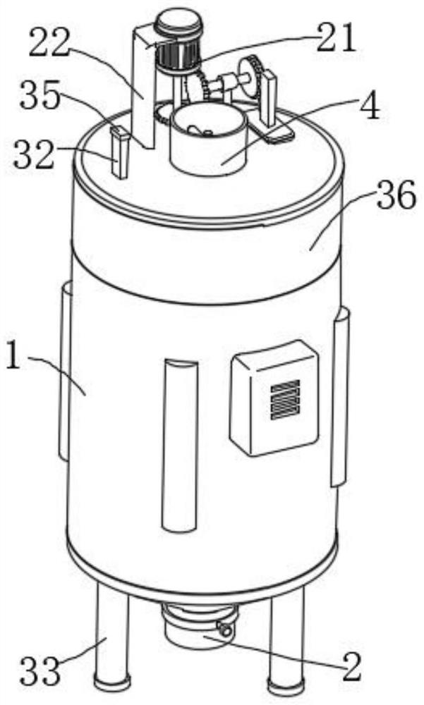
[0037] Such as figure 1 , figure 2 , image 3 , Figure 4 , Figure 5 , Image 6As shown, this embodiment proposes an energy-saving and environment-friendly sewage treatment system, including a lower casing 1 arranged horizontally, the bottom of the lower casing 1 is funnel-shaped, and a water outlet pipe 2 is fixed vertically on the bottom of the lower casing 1, and the water outlet pipe 2 A valve 3 is installed, an upper casing 36 is mounted on the upper end surface of the lower casing 1, and a water inlet 4 is vertically fixed on the upper wall of the upper casing 36, and the water inlet 4 is vertically provided with a valve extending into the lower casing 1. The main shaft 5, the main shaft 5 is installed on the inner wall of the water inlet 4 through a connecting piece, the connecting piece includes a collar 19 which is rotatably sleeved on the outer side wall of the main shaft 5, and the outer side wall of the collar 19 is connected to the water inlet 4 through the ...

Embodiment 2

[0039] The scheme in embodiment 1 is further introduced below in combination with specific working methods, see the following description for details:

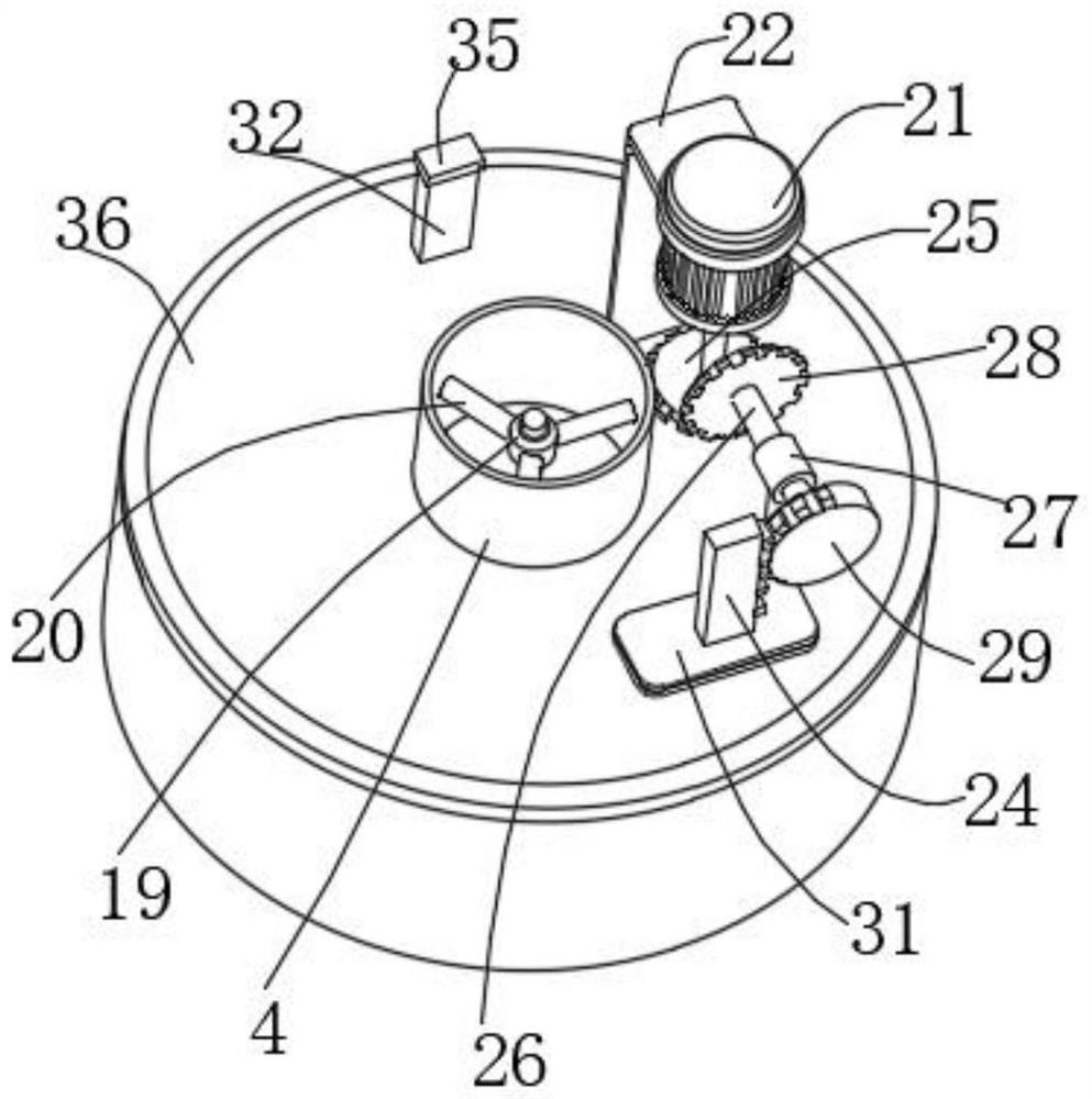
[0040] Such as figure 1 , image 3 , Figure 4 As shown, as a preferred embodiment, on the basis of the above method, the linkage mechanism includes a rack 24 fixed vertically on the upper end surface of the upper ring 16, the rack 24 moves through the upper housing 36, and the output shaft of the motor 21 An active helical gear 25 is fixedly sleeved horizontally on the outer side wall above the upper housing 36 , and a bracket 27 connected to the transmission shaft 26 is fixed vertically on the upper end of the upper housing 36 . The transmission shaft 26 is close to the drive shaft 25 . One end is vertically fixedly installed with a driven helical gear 28 meshed with the driving helical gear 25, and one end of the transmission shaft 26 away from the driven helical gear 28 is vertically fixedly installed with an incomplete ...

Embodiment 3

[0042] The schemes in Embodiment 1 and Embodiment 2 will be further introduced in combination with specific working methods, see the following description for details:.

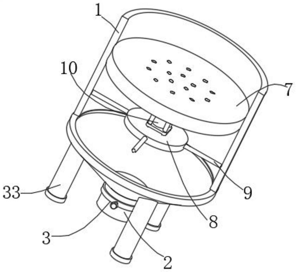
[0043] Such as figure 1 , figure 2 , Figure 4 , Figure 5 , Image 6 As shown, as a preferred embodiment, on the basis of the above method, the length of the water blocking rod 12 is the same as the thickness of the mesh plate 7, and the plurality of water blocking rods 12 correspond to the meshes of the mesh plate 7 one by one, and the scraper 6 The upper end surface is inclined, the scraper 6 is fan-shaped at 90 degrees, and the length of the water blocking rod 12 is set to ensure that the scraper 6 will not collide with the water blocking rod 12 during the rotating operation, so as to ensure the realization of the function of the device. 12 can not only be used to control the opening and blocking of the mesh plate 7, but also can be used to clean the mesh of the mesh plate 7. The upper end surface of...


PUM


Abstract

The invention relates to an energy-saving and environment-friendly sewage treatment system and a sewage treatment method, and belongs to the field of sewage treatment. a scraping plate and a spiral stirrer are arranged to be matched with a circular ring, the scraping plate scrapes sewage treatment agent particles on a bottom layer, and the spiral stirrer is used for drainage to drive the sewage treatment agent particles to move upwards; and meanwhile, mixing of sewage and a sewage treatment agent is promoted through the up-down moving circular ring, so that the mixing effect of the device is better, a motor is used for driving multiple assemblies to move differently, power equipment is saved, the equipment cost is reduced, and the system is more energy-saving and environment-friendly.

Description

technical field [0001] The invention relates to an energy-saving and environment-friendly sewage treatment system and a sewage treatment method, belonging to the field of sewage treatment. Background technique [0002] During sewage treatment, the corresponding sewage treatment agent will be added to react with the sewage, and the toxic and harmful substances will be converted into sediment and filtered out. However, the existing sewage treatment device lacks an automatic cleaning device for the filter device. When the sewage reacts, the sediment and debris are relatively For a long time, the filter device will be blocked, and the treated sewage cannot be discharged. At the same time, the cleaning of the filter device is more troublesome, which affects the function realization of the device. [0003] Therefore, we make improvements to this, and propose an energy-saving and environment-friendly sewage treatment system and a sewage treatment method. Contents of the invention...

Claims


Application Information

Patent Timeline
Patent Type & Authority Applications(China)
IPC IPC(8): C02F9/04
CPCC02F1/5281C02F1/52C02F1/001C02F2303/16C02F2303/14
Inventor 张素萍
Owner 张素萍
Why Eureka
Try Eureka