
A Sectional Joint Structure of Prefabricated Underground Diaphragm Wall

A technology of underground diaphragm wall and joint structure, applied in basic structure engineering, sheet pile wall, building and other directions, can solve the problems of poor stability, reduced use effect, unfavorable concrete pouring, etc., to strengthen the connection stability, reduce the impact of impact, Not easy to loosen

Active Publication Date: 2022-06-24
GUANGDONG YUANTIAN ENG
View PDF7 Cites 0 Cited by
  • Summary
  • Abstract
  • Description
  • Claims
  • Application Information

AI Technical Summary

Problems solved by technology

[0003] In the prior art, the stability of the diaphragm wall structure is poor when pouring concrete, which makes the diaphragm wall structure prone to loosening, which is not conducive to the pouring of concrete, and greatly reduces its use effect

Method used


Image

  • A Sectional Joint Structure of Prefabricated Underground Diaphragm Wall
  • A Sectional Joint Structure of Prefabricated Underground Diaphragm Wall
  • A Sectional Joint Structure of Prefabricated Underground Diaphragm Wall

Examples


Embodiment

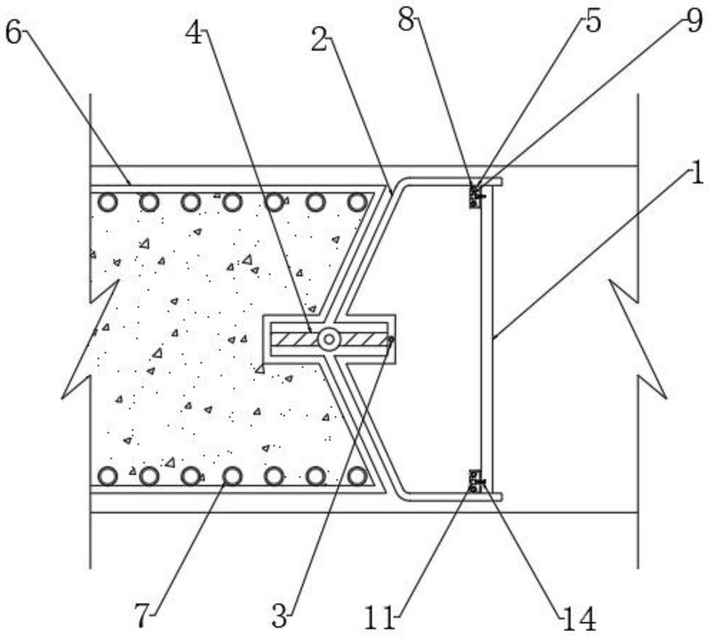
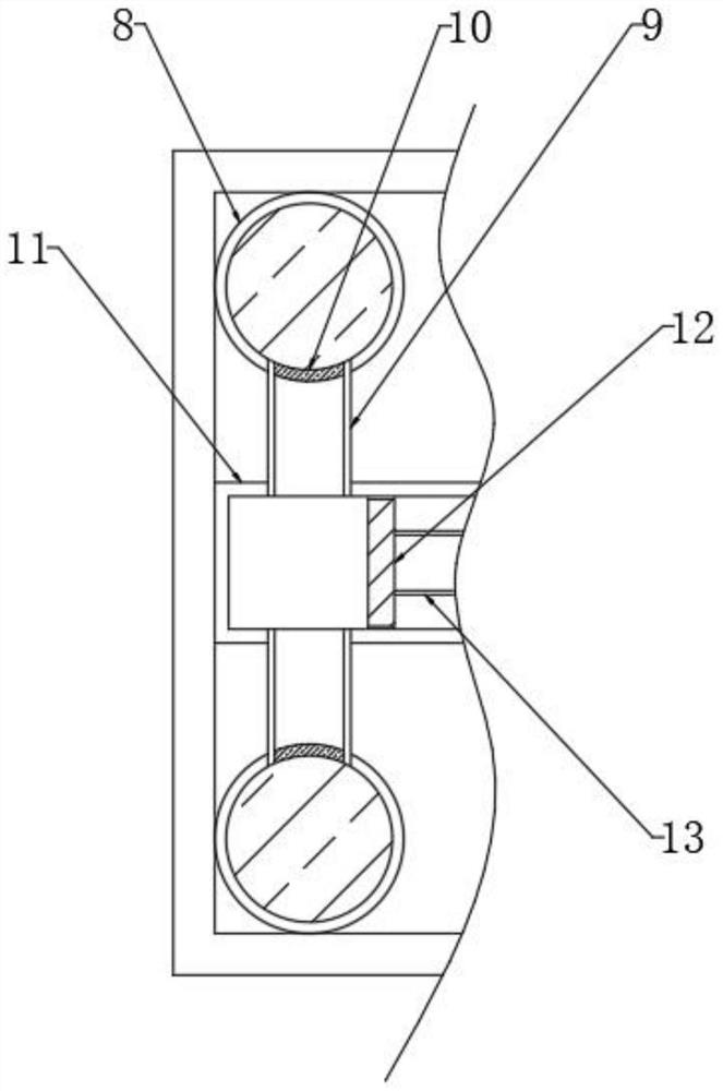
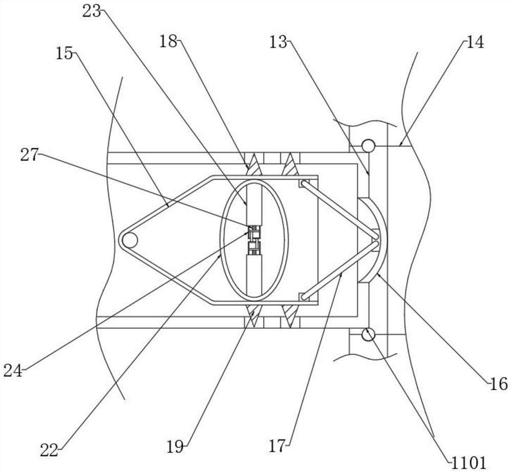
[0041] see Figure 1-6 , a sub-section joint structure of a prefabricated underground diaphragm wall, comprising a removable steel plate 1, the outer end of the removable steel plate 1 is installed with a pre-formed steel plate 2, and the inner wall of the pre-formed steel plate 2 is fixedly connected with two upper and lower symmetrical limit stop frames 5. The outer end of the preformed steel plate 2 is installed with a horizontal steel bar 6, the outer end of the horizontal steel bar 6 is fixedly connected with a longitudinal steel bar 7, the outer end of the horizontal steel bar 6 is installed with a rubber water stop 4, and the outer end of the preformed steel plate 2 is installed There is a shaft sleeve and pin kit 3, and the limit stop frame 5 is fixedly connected with two up and down symmetrical liquid storage balls 8. The liquid storage ball 8 is filled with carbon dioxide aqueous solution, and the inner wall of the limit stop frame 5 is fixedly connected with a straig...


PUM


Abstract

The invention discloses a segmented joint structure of a prefabricated underground continuous wall, which belongs to the field of continuous walls. When pouring concrete, the carbon dioxide aqueous solution in the liquid storage ball is shaken to promote the carbon dioxide to overflow into the straight cylinder, and the piston is pushed to squeeze the fixed pipe and extend to the At the same time, when the flexible sheet is squeezed to the vertical state, the two oblique rods are driven to squeeze the reed, so that the limit block extends into the limit groove seat, and punctures the film, so that the wet water The sticky layer becomes viscous when it encounters water, which promotes the tight adhesion and fixation of the limit block and the limit groove seat, strengthening the connection stability, and the stretching capsule is stretched along with the reed, so that the thick rod pulls the moving plate and the pulling rod to move , prompting the phase change support rod to be stretched, and under the action of tension, it changes from soft to hard to form a rigid support rod, which not only effectively slows down the impact of concrete pouring, but also prevents the adhesion of the limit block and the limit slot seat. The limit provides support firmness and enhances connection stability.

Description

technical field [0001] The present invention relates to the field of continuous walls, and more particularly, to a prefabricated underground continuous wall and a segmented joint structure. Background technique [0002] Diaphragm wall, also known as underground diaphragm wall, is a kind of trenching machine used on the ground for foundation engineering. Along the peripheral axis of the deep excavation project, under the condition of mud wall protection, a narrow and long deep trench is excavated. The steel cage is suspended in the groove, and then the underwater concrete is poured by the conduit method to form a unit groove section. This is done section by section, and a continuous reinforced concrete wall is built underground to serve as water interception, anti-seepage, load-bearing and water-retaining. structure. [0003] In the prior art, the continuous wall structure has poor stability when pouring concrete, so that the continuous wall structure is prone to loosening, ...

Claims


Application Information

Patent Timeline
Patent Type & Authority Patents(China)
IPC IPC(8): E02D5/10E02D5/12E02D5/14
CPCE02D5/10E02D5/12E02D5/14
Inventor 谢志杰刘则邹黄茂兴刘志军饶明文罗海腾陆金伦刘忠干谢宝如詹壮平邱财元
Owner GUANGDONG YUANTIAN ENG
Learn More