
Convenient-to-mount spliced steel structure frame for building support

A splicing and steel structure technology, which is applied in the direction of building structure, building, building structure support, etc., can solve the problems of danger, inconvenient material transfer method, insufficient scaffolding installation and operation process, etc., and achieve convenient disassembly and assembly, flexible adjustment and convenience , to avoid the effect of inconvenient material transfer

Pending Publication Date: 2022-02-11
JIANGSU SUZHONG CONSTR GROUP
View PDF6 Cites 0 Cited by
  • Summary
  • Abstract
  • Description
  • Claims
  • Application Information

AI Technical Summary

Problems solved by technology

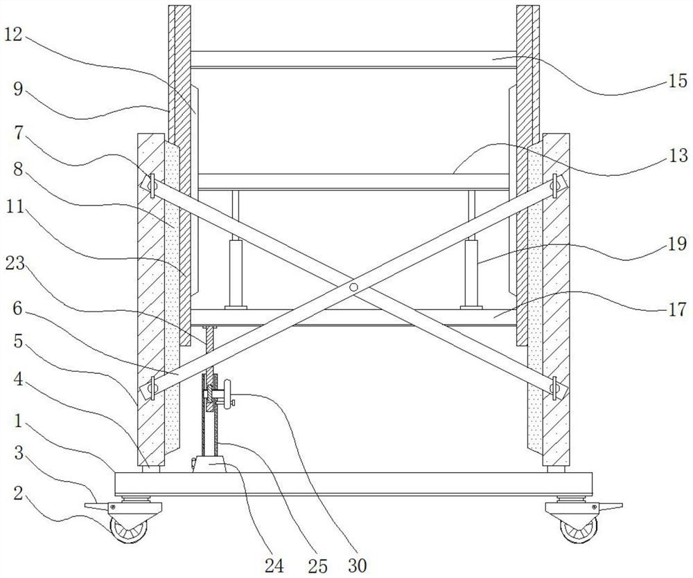
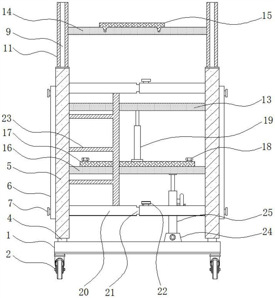
[0004] The purpose of the present invention is to provide a spliced ​​steel structure frame that is easy to install for building support, to solve the problem that most of the scaffolding structures currently used for building construction proposed in the background technology are similar, although they can meet the construction requirements on the whole, but There are still some deficiencies in the actual construction process. For example, if ordinary scaffolding wants to construct a higher position during construction operations, it needs to be lifted through the two-story or even three-story superposition of the steel structure, which is not only dangerous It is time-consuming and labor-intensive, and at the same time, it is quite inconvenient for the delivery method of materials. In addition, there are also some shortcomings in the installation and operation process of scaffolding.

Method used


Image

  • Convenient-to-mount spliced steel structure frame for building support
  • Convenient-to-mount spliced steel structure frame for building support
  • Convenient-to-mount spliced steel structure frame for building support

Examples


Embodiment Construction

[0026] The following will clearly and completely describe the technical solutions in the embodiments of the present invention with reference to the accompanying drawings in the embodiments of the present invention. Obviously, the described embodiments are only some, not all, embodiments of the present invention. Based on the embodiments of the present invention, all other embodiments obtained by persons of ordinary skill in the art without making creative efforts belong to the protection scope of the present invention.

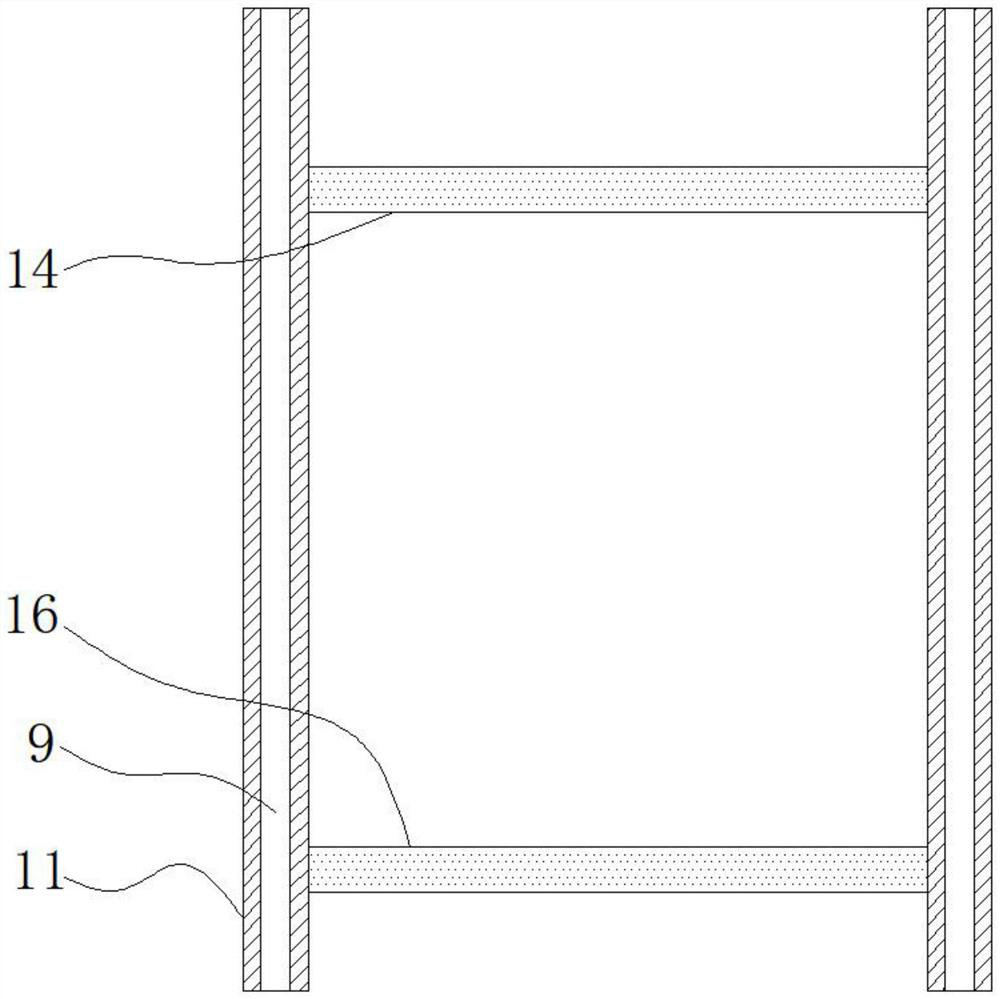
[0027] see Figure 1-5, the present invention provides a technical solution: an easy-to-install spliced ​​steel structure frame for building support, including a mobile base 1, universal wheels 2, foot brakes 3, fixed pins 4, main poles 5, and diagonal struts 6 , the first screw 7, the slide rail 8, the fitting 9, the ball 10, the secondary pole 11, the chute 12, the conveying plate 13, the first cross bar 14, the pedal 15, the second cross bar 16, the auxilia...


PUM


Abstract

The invention relates to a convenient-to-mount spliced steel structure frame for building support, which comprises a movable base and a slide rail, universal wheels are arranged at four corners of the lower end of the movable base, a foot brake is arranged on one side of each universal wheel, fixing pins are arranged at four corners of the upper end of the movable base, and main vertical rods are arranged at the upper ends of the fixing pins. An inclined supporting rod is arranged on one side of the main vertical rod, a first threaded rod is arranged at the joint of the inclined supporting rod and the main vertical rod, the sliding rail is arranged on the inner side of the main vertical rod, and an embedding piece is arranged on the inner side of the sliding rail. The spliced steel structure frame for building supporting is provided with the embedded parts, and the auxiliary vertical rods need to be frequently adjusted in height during operation, so that the main effect of the sliding rails is that the embedded parts are in sliding connection through the balls, and the main vertical rods and the auxiliary vertical rods are in up-and-down sliding connection; and the embedding piece and the auxiliary vertical rod can move up and down more smoothly through mutual matching of the sliding rails and the balls.

Description

technical field [0001] The invention relates to the technical field of building support steel structure frames, in particular to an easy-to-install spliced ​​steel structure frame for building support. Background technique [0002] Steel structure is a structure composed of steel materials, which is one of the main types of building structures. The structure is mainly composed of steel beams, steel columns and steel trusses made of section steel and steel plates. Welding seam, bolt or rivet connection, because of its light weight and easy construction, is widely used in large-scale factories and venues and super high-rise fields, while scaffolding supporting steel structures are commonly used components in building construction, and for the disassembly and assembly of scaffolding New requirements have also been put forward on the convenience of operation. [0003] At present, most of the scaffolding structures used in building construction are similar. Although they can mee...

Claims


Application Information

Patent Timeline
Patent Type & Authority Applications(China)
IPC IPC(8): E04G1/24E04G1/22E04G1/15E04G5/00
CPCE04G1/24E04G1/22E04G1/15E04G5/003E04G2001/242
Inventor 于海峰沈清尹陈君姜传舟
Owner JIANGSU SUZHONG CONSTR GROUP
Learn More