
Air compression air inlet device for vehicle fuel cell

A fuel cell and air compression technology, used in fuel cells, fuel cell additives, pump devices, etc., can solve the problem of reducing the mechanical efficiency and safety and reliability of air compressors, difficult to ensure compressed air flow, and easy wear of thrust bearings. problems, to eliminate mechanical losses and thrust bearing wear problems, improve overall efficiency, and eliminate axial loads

Pending Publication Date: 2022-02-11
BEIJING INSTITUTE OF TECHNOLOGYGY
View PDF0 Cites 0 Cited by
  • Summary
  • Abstract
  • Description
  • Claims
  • Application Information

AI Technical Summary

Problems solved by technology

Although it is easy to achieve a high pressure ratio, it is difficult to ensure sufficient compressed air flow, and it is still difficult to balance the axial force borne by the impellers of the low-pressure stage and the high-pressure stage. Large axial thrust, the thrust bearing is easy to wear, and the thrust plate needs to be relatively large in size, so the bearing efficiency is relatively low and the flow rate is relatively small, which is half of the parallel type, which reduces the mechanical efficiency and safety reliability of the air compressor

Method used


Image

  • Air compression air inlet device for vehicle fuel cell
  • Air compression air inlet device for vehicle fuel cell

Examples


Embodiment Construction

[0017] The technical solutions in the embodiments of the present invention will be clearly and completely described below. Obviously, the described embodiments are only some of the embodiments of the present invention, but not all of them. Based on the embodiments of the present invention, all other embodiments obtained by persons of ordinary skill in the art without making creative efforts belong to the protection scope of the present invention.

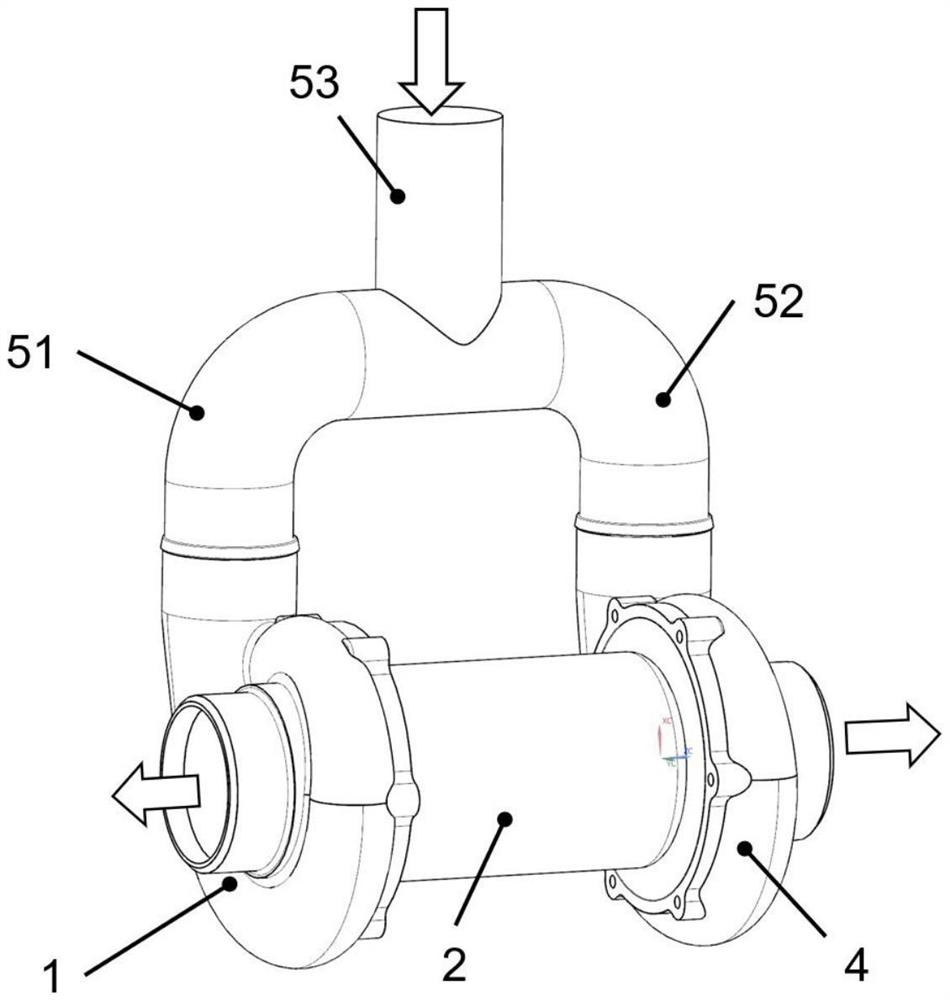
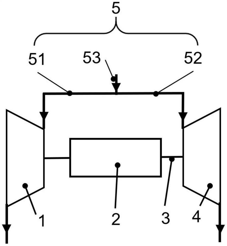
[0018] The embodiment of the present invention discloses an air compression intake device for a vehicle fuel cell, comprising:

[0019] A transmission shaft 3, the first centrifugal compressor 1 and the second centrifugal compressor 4 are drive-connected to both ends of the transmission shaft 3 respectively; the first centrifugal compressor 1 and the second centrifugal compressor 4 are the same.

[0020] Three-way pipeline 5, described three-way pipeline 5 comprises first exhaust pipe 51, second exhaust pipe 52 and exhaust main pipe...


PUM


Abstract

The invention discloses a high-flow high-speed motor direct-drive type intake air compression device for a vehicle fuel cell, which comprises a high-speed motor, a rotor shaft and a three-way pipeline, wherein the high-speed motor drives a motor rotor and a rotor shaft integrated with the motor rotor to rotate at a high speed; the two ends of the rotor shaft are connected with a first centrifugal gas compressor and a second centrifugal gas compressor respectively, the first gas compressor and the second gas compressor are symmetrically arranged on the two sides of the motor, and impellers of the first gas compressor and the second gas compressor are driven by the rotor shaft to coaxially rotate at a high speed; and the three-way pipeline comprises a first exhaust pipe, a second exhaust pipe and an exhaust main pipe which are integrally manufactured, the first exhaust pipe is communicated with an exhaust port of the first centrifugal compressor, the second exhaust pipe is communicated with an exhaust port of the second centrifugal compressor, and the first exhaust pipe and the second exhaust pipe are communicated to the exhaust main pipe. The device can realize high-flow air pressurization of a high-power fuel cell, realizes axial force self-balance of an air compressor while realizing high pressure ratio and high flow of inlet air, effectively solves the problems of efficiency reduction and wear of a thrust bearing caused by the thrust bearing, and can effectively improve the efficiency and the working reliability of the air compression air inlet device.

Description

technical field [0001] The invention relates to an air compression air intake device for a vehicle fuel cell, belonging to the field of fuel cell intake systems for new energy vehicles. Background technique [0002] The fuel cell is an important new energy vehicle power component. Currently, the commonly used air compression intake device for fuel cells is mainly driven by a high-speed motor to meet the demand for pressurization of the intake air. As the fuel cell stack power increases and the power density continues to increase, the boost ratio and flow rate of the intake air also tend to increase gradually. [0003] At present, the commonly used fuel cell intake booster air compressor (air compressor) mostly adopts a single-stage centrifugal air compressor arranged on one side and a series type with a low-pressure centrifugal compressor and a high-pressure centrifugal compressor on both sides. Two-stage centrifugal air compressor. Among them, the single-stage centrifugal...

Claims


Application Information

Patent Timeline
Patent Type & Authority Applications(China)
IPC IPC(8): F04D17/12F04D25/06F04D29/051H01M8/04111H01M8/04082
CPCF04D17/12F04D25/06F04D29/051H01M8/04111H01M8/04201Y02E60/50Y02P70/50
Inventor 祁明旭张虹王鹏霄
Owner BEIJING INSTITUTE OF TECHNOLOGYGY
Features
  • Generate Ideas
  • Intellectual Property
  • Life Sciences
  • Materials
  • Tech Scout
  • Unparalleled Data Quality
  • Higher Quality Content
  • 60% Fewer Hallucinations
Learn More