Plugging device for municipal pipeline port

A technology for plugging devices and municipal pipelines, which is applied in the direction of pipe components, pipes/pipe joints/fittings, mechanical equipment, etc. It can solve the problems of inconvenient installation and disassembly, time-consuming, energy-consuming, unstable, etc., and achieve a stable plugging effect. Easy and efficient installation, stable adjustment effect

Active Publication Date: 2022-02-11
韶关市第一建筑工程有限公司
View PDF8 Cites 5 Cited by
  • Summary
  • Abstract
  • Description
  • Claims
  • Application Information

AI Technical Summary

Problems solved by technology

[0003] The current pipeline sealing device usually adopts a cover plate or a single airbag. The cover plate is generally equipped with a sealing ring to cooperate with the inner wall of the pipeline, and the sealing ring is inserted into the pipeline. When dismantling, the large friction between the sealing ring and the inner wall of the pipe requires heavy equipment such as excavators or bulldozers to force (jack) the sealing ring into the pipe. Pulling out the pipe is inconvenient for installation and disassembly, and consumes time and energy; the single airbag is mostly made of polymer materials such as rubber. When using the airbag, the airbag is placed in the pipe to inflate the airbag. After the airbag is inflated, it touches the inner wall of the pipe , so as to realize the blockage of the pipeline, but the single airbag needs to be inflated with inflatable equipment during use, which consumes time and energy. The problem of poor plugging effect and low plugging reliability
[0004] In view of the above-mentioned related technologies, the inventor believes that the existing blocking device has the defects of time-consuming and energy-consuming use and unstable blocking effect

Method used


Image

  • Plugging device for municipal pipeline port
  • Plugging device for municipal pipeline port
  • Plugging device for municipal pipeline port

Examples


Embodiment Construction

[0037] The following is attached Figure 1-4 The application is described in further detail.

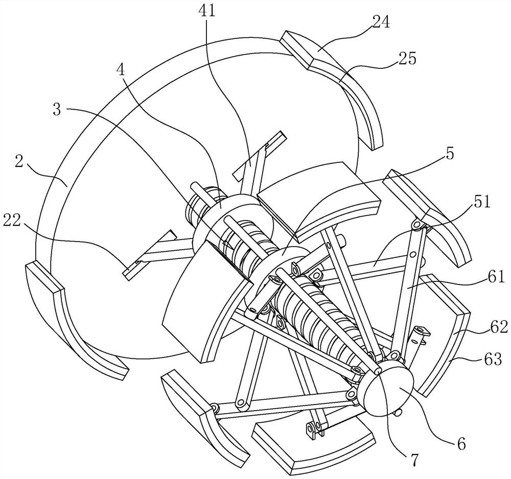
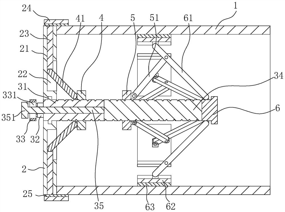
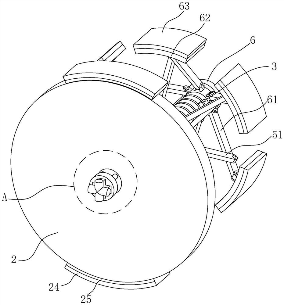
[0038] The embodiment of the present application discloses a plugging device for a municipal pipeline port. refer to figure 1 and figure 2 , the plugging device includes an outer end cover 2 and a screw rod 3, the outer end cover 2 is a circular flat plate, and the outer end cover 2 is in close contact with the nozzle of the pipeline 1; the outer end cover is provided with a clamp for clamping the outer wall of the pipeline 1 Tightening mechanism; the screw rod 3 is perpendicular to the outer end cover 2, one end of the screw rod 3 is rotationally connected with the middle part of the outer end cover 2, and the other end extends into the interior of the pipeline 1 along the horizontal direction, and the screw rod 3 is provided with a plurality of holes for pressing against the inner wall of the pipeline 1 block 62.

[0039] refer to figure 2 and image 3 , the screw 3 include...


PUM


Abstract

The invention relates to a plugging device for a municipal pipeline port. The plugging device comprises a screw rod and an outer end cover used for tightly abutting against the port of the pipeline, the screw rod is perpendicular to the outer end cover, one end of the screw rod is rotationally connected with the outer end cover, the other end of the screw rod extends into the pipeline, and a clamping mechanism used for clamping the outer side wall of the pipeline is arranged on the outer end cover; the end, away from the outer end cover, of the screw rod is fixedly connected with a fixing block, the fixing block is provided with a plurality of abutting rods in the circumferential direction, one end of each abutting rod is hinged to the fixing block, and the other end of each abutting rod is hinged to an abutting block used for abutting against the inner wall of the pipeline; the ends, away from the fixing block, of the abutting rods are mutually gathered or dispersed towards the center line of the screw rod; and the screw rod is provided with an expansion assembly used for driving the abutting rods to disperse so that the abutting blocks can abut against the inner wall of the pipeline. The plugging device has the effects that the stability of the plugging effect of the plugging device is improved, installation is convenient and fast, and energy consumption is reduced.

Description

technical field [0001] The present application relates to the technical field of pipe plugging, in particular to a plugging device for municipal pipe ports. Background technique [0002] During the production operation, in order to prevent sand, water, rats, etc. from entering the pipeline during the production process, a pipeline blocking device is usually installed at the end of the pipeline. [0003] The current pipeline sealing device usually adopts a cover plate or a single airbag. The cover plate is generally equipped with a sealing ring to cooperate with the inner wall of the pipeline, and the sealing ring is inserted into the pipeline. When dismantling, the large friction between the sealing ring and the inner wall of the pipe requires heavy equipment such as excavators or bulldozers to force (jack) the sealing ring into the pipe. Pulling out the pipe is inconvenient for installation and disassembly, and consumes time and energy; the single airbag is mostly made of ...

Claims


Application Information

Patent Timeline
Patent Type & Authority Applications(China)
IPC IPC(8): F16L55/115
CPCF16L55/1157
Inventor 蒙家平黄扬纯林超范宇恒刘畅
Owner 韶关市第一建筑工程有限公司
Why Eureka
Try Eureka