
Laser feeding device

A laser and feeding technology, which is applied in metal processing, metal processing equipment, manufacturing tools, etc., can solve the problems of high labor intensity and low work efficiency of the staff, and achieve good connection effect, high work smoothness, and low labor intensity Effect

Pending Publication Date: 2022-02-15
哈工大机器人南昌智能制造研究院
View PDF0 Cites 0 Cited by
  • Summary
  • Abstract
  • Description
  • Claims
  • Application Information

AI Technical Summary

Problems solved by technology

[0002] An optical sensor includes a copper tube, in which there are lenses, springs, lasers and other devices in sequence. At this stage, the assembly of the above devices is done manually. First, the copper tube is vertically inserted into a After that, put lenses, springs, lasers and other components into the copper tubes one by one. Not only the labor intensity of the staff is high, but also the work efficiency is low. In order to solve the above problems, it is necessary to design a rotary mechanized assembly For the equipment, the assembly process of each component is arranged in a circular order. Since multiple lasers are contained in the box and need to be taken out of the box one by one during assembly, at the same time, because the pins of the laser are placed downwards in the box, and During assembly, it is necessary to orient the pins of the laser to complete the assembly. Therefore, in order to ensure the continuity of the work of the laser at the assembly station and cater to the assembly rhythm of other processes, a pair of lasers must be designed for structural

Method used


Image

  • Laser feeding device
  • Laser feeding device
  • Laser feeding device

Examples


Embodiment Construction

[0043] The present invention will be described in further detail below through specific examples.

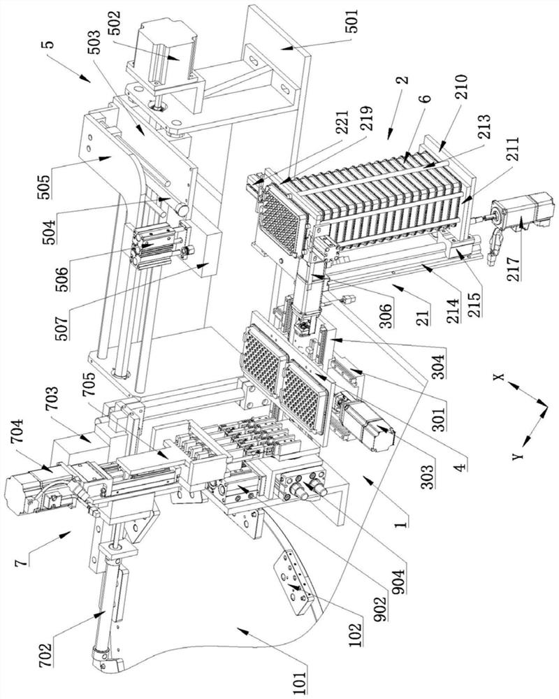
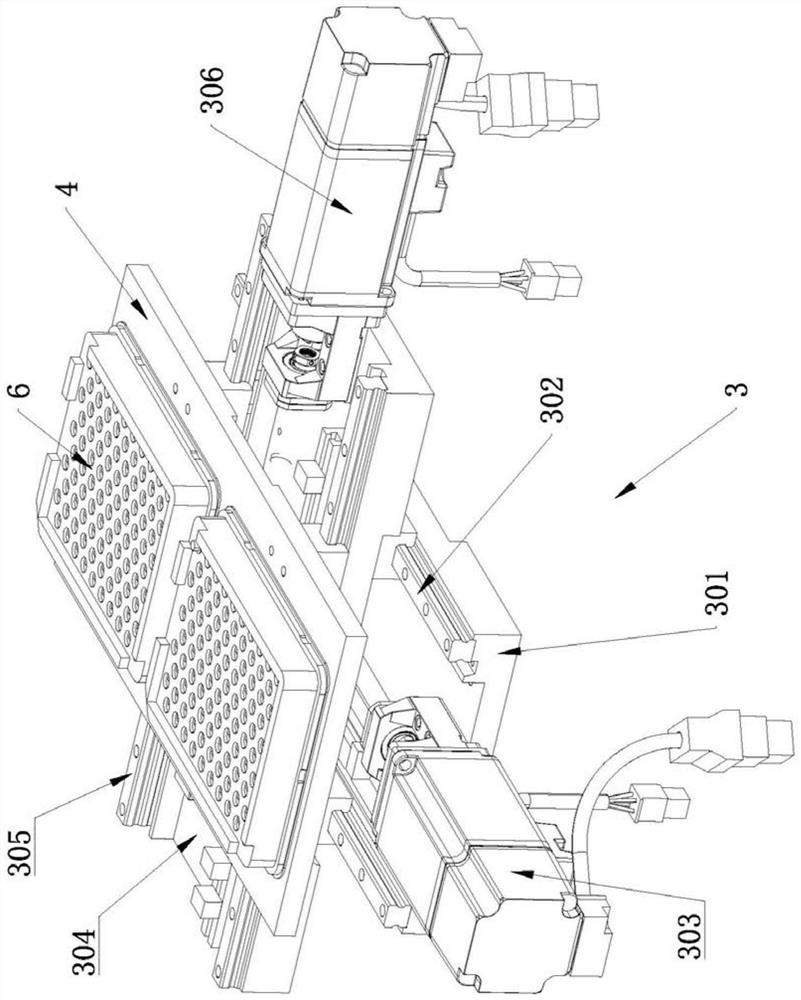
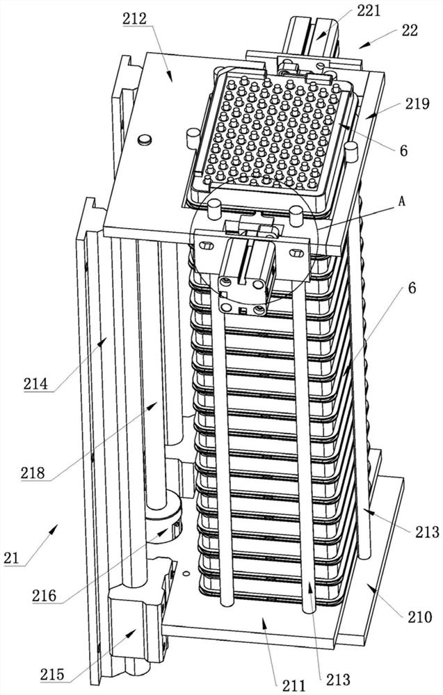
[0044] Such as figure 1 As shown, a laser supply device, a laser supply device, includes a frame 1, on which a turntable driven by a drive device (such as a combined drive structure of a motor and a reducer, not shown in the figure) is mounted on the frame 1 101, the frame 1 is provided with a vertical box storage rack 2, the frame 1 located downstream of the box storage rack 2 is provided with an adjustment mechanism 3, and the adjustment mechanism 3 is provided with a box placement platform 4. A box body transfer mechanism 5 for transferring the box body 6 between the box body placement table 4 and the box body storage rack 2 is provided on the frame 1 located on one side of the box body storage rack 2; the turntable 101 The upper annular array has a plurality of copper pipe material holders 102 (a plurality of holes for inserting copper pipes and vertically arranged holes ar...


PUM


Abstract

The invention discloses a laser feeding device which comprises a rack, wherein a rotating disc driven by a driving device is rotationally installed on the rack, a vertically-arranged box body storage and supply frame is further arranged on the rack, an adjusting mechanism is arranged on the portion, located on the downstream of the box body storage and supply frame, of the rack, a box body accommodating table is arranged on the adjusting mechanism, and a box body transfer mechanism for transferring a box body is arranged on the rack on one side of the box body storage and supply frame; a plurality of copper pipe material bases are annularly arranged on the rotating disc, and a clamping and overturning mechanism is arranged on the rack on the periphery of the rotating disc and on the downstream of the adjusting mechanism; and the rack is further provided with a clamping and transferring mechanism used for transferring a laser. According to the laser feeding device, mechanical automatic feeding of the box body accommodating the laser is achieved, the laser in the box body is adjusted in position, picked up, turned over and clamped and moved, and the purpose of continuously feeding and feeding the laser is achieved; and the connection effect among all procedures is good, the working smoothness and the working efficiency are high, and the labor intensity of workers is low.

Description

technical field [0001] The invention belongs to the technical field of sensor assembly, in particular to a laser supply device. Background technique [0002] An optical sensor includes a copper tube, in which there are lenses, springs, lasers and other devices in sequence. At this stage, the assembly of the above devices is done manually. First, the copper tube is vertically inserted into a After that, put lenses, springs, lasers and other components into the copper tubes one by one. Not only the labor intensity of the staff is high, but also the work efficiency is low. In order to solve the above problems, it is necessary to design a rotary mechanized assembly For the equipment, the assembly process of each component is arranged in a circular order. Since multiple lasers are contained in the box and need to be taken out of the box one by one during assembly, at the same time, because the pins of the laser are placed downwards in the box, and During assembly, the pins of th...

Claims


Application Information

Patent Timeline
Patent Type & Authority Applications(China)
IPC IPC(8): B23P19/00
CPCB23P19/002B23P19/006
Inventor 易均萍刘晓东戴文军沈一博熊磊
Owner 哈工大机器人南昌智能制造研究院
Learn More