Multifunctional fixing tool for machining

A fixed tooling and machining technology, applied in workpiece clamping devices, manufacturing tools, etc., can solve the problems of inconvenient cleaning and collection of debris, deviation of the final position of the workpiece, and intolerance to vibration, etc., to increase the fixing effect, avoid Processing effect, the effect of increasing practicality

Active Publication Date: 2022-02-15
浙江荣孚工智能科技有限公司
View PDF5 Cites 1 Cited by
  • Summary
  • Abstract
  • Description
  • Claims
  • Application Information

AI Technical Summary

Problems solved by technology

[0003]The existing tooling specifications are fixed, and a single tooling mechanism can only be used to fix parts of corresponding specifications, which has certain limitations in use; although the existing part solves In the scheme, multiple jaws or clamping joints set in multiple sub-regions are used, and each clamping jaw or clamping joint is equipped with a separate driving structure, so as to realize different telescopic feed control of different driving structures for workpieces of different sizes , and in most operating scenarios, the parts to be processed are regular bodies, such as cubes or circles, cylinders, or spheres. Therefore, to treat such workpieces, each driving mechanism needs to drive each jaw to accurately and precisely clamp the workpiece. Each position, so that the workpiece is located at the center of the base without offset, but in the actual work process, the start-up time of each jaw drive mechanism and the final output expansion and contraction cannot be completely the same, although the last multiple The jaws will clamp the workpiece, but it will cause the final stop position of the workpiece to shift after being clamped. The existing centering optical detection device or a center reference rod is required to set the centering reference of the workpiece, but the optical detection The device is generally expensive and not resistant to vibration, while the central reference rod requires an opening at the bottom, making it difficult to clean and collect debris during processing

Method used


Image

  • Multifunctional fixing tool for machining
  • Multifunctional fixing tool for machining
  • Multifunctional fixing tool for machining

Examples


Embodiment Construction

[0025] The following will clearly and completely describe the technical solutions in the embodiments of the present invention with reference to the accompanying drawings in the embodiments of the present invention. Obviously, the described embodiments are only some of the embodiments of the present invention, not all of them. Based on the embodiments of the present invention, all other embodiments obtained by persons of ordinary skill in the art without making creative efforts belong to the protection scope of the present invention.

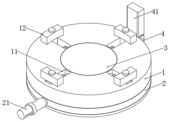
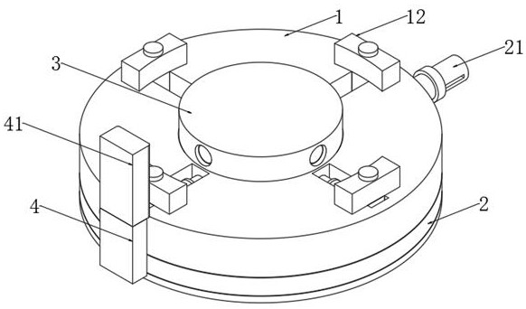
[0026] according to Figure 1-5 The shown multifunctional fixed tooling for machining includes a base 1: the outer surface of the base 1 is covered with a mounting ring 2, the mounting ring 2 is rotatably connected to the base 1, and the inside of the base 1 An inner platform 3 is arranged in the center, a mounting plate 4 is fixedly mounted on one side of the mounting ring 2, a handle 21 is fixedly mounted on the other side of the mounting ring ...


PUM


Abstract

The invention discloses a multifunctional fixing tool for machining, and particularly relates to the field of machining, the multifunctional fixing tool comprises a base, and the outer surface of the base is sleeved with a mounting ring. By arrangement of the base, clamping plates, rotary knobs and first sliding blocks, the two sides of the clamping plates are designed into curved surfaces and planes correspondingly, adjustment can be conducted according to the shape of a part, and when the machined part is of an annular structure, an air cylinder in the base can be started to drive an inner table to be pushed out of a containing groove and located in the annular part; then a second electromagnet at one end of a push rod is started, the second electromagnet can move towards one side of a first baffle ring through magnetic force, so that the push rod is pushed outwards, an ejector block at the other end of the push rod abuts against the inner wall of the part, the ejector block is made of rubber and can be well attached to the inner wall of the part, internal and external fixation is conducted through an outer side clamping plate, and the fixing effect is greatly improved; and parts of different specifications can be fixed, and the practicability of the fixing tool is greatly improved.

Description

technical field [0001] The invention relates to the field of machining, and more specifically, the invention relates to a multifunctional fixed tool for machining. Background technique [0002] Tooling, that is, process equipment, refers to the general term for tools and equipment used in the manufacturing process. It includes knives, measuring tools, inspection tools, fixtures, molds, station equipment, etc., and is an important equipment for auxiliary processing and manufacturing. [0003] The existing tooling specifications are fixed, and a single tooling mechanism can only be used to fix parts of the corresponding specifications, which has certain limitations in use; although some existing solutions use multiple jaws or clamps set in multiple sub-regions Joints are set, and each jaw or clamping joint is equipped with a separate drive structure, so as to realize different telescopic feed control of different drive structures for workpieces of different sizes, and in most ...

Claims


Application Information

Patent Timeline
Patent Type & Authority Applications(China)
IPC IPC(8): B25B11/00
CPCB25B11/002Y02P70/10
Inventor 甘武林
Owner 浙江荣孚工智能科技有限公司
Why Eureka
Try Eureka