Composite material rotary fiber placement device and use method

A technology of composite material and wire laying, which is applied in the field of composite material forming auxiliary equipment, can solve the problems that the forming mold cannot be designed as a rotary structure, is not a rotary body, and has high manufacturing costs, so as to save curing space, increase utilization rate, and save molds The effect of the design

Active Publication Date: 2022-02-15
XI'AN AIRCRAFT INTERNATIONAL
View PDF7 Cites 0 Cited by
  • Summary
  • Abstract
  • Description
  • Claims
  • Application Information

AI Technical Summary

Problems solved by technology

[0005] Most of the composite material parts are not rotating bodies, and their forming molds cannot be designed as rotating bodies.
A small amount of common fully-enclosed or partially-enclosed composite material parts often require forming molds to be divided into pieces, the design is complex, and the manufacturing cost is high.

Method used


Image

  • Composite material rotary fiber placement device and use method
  • Composite material rotary fiber placement device and use method
  • Composite material rotary fiber placement device and use method

Examples


Embodiment Construction

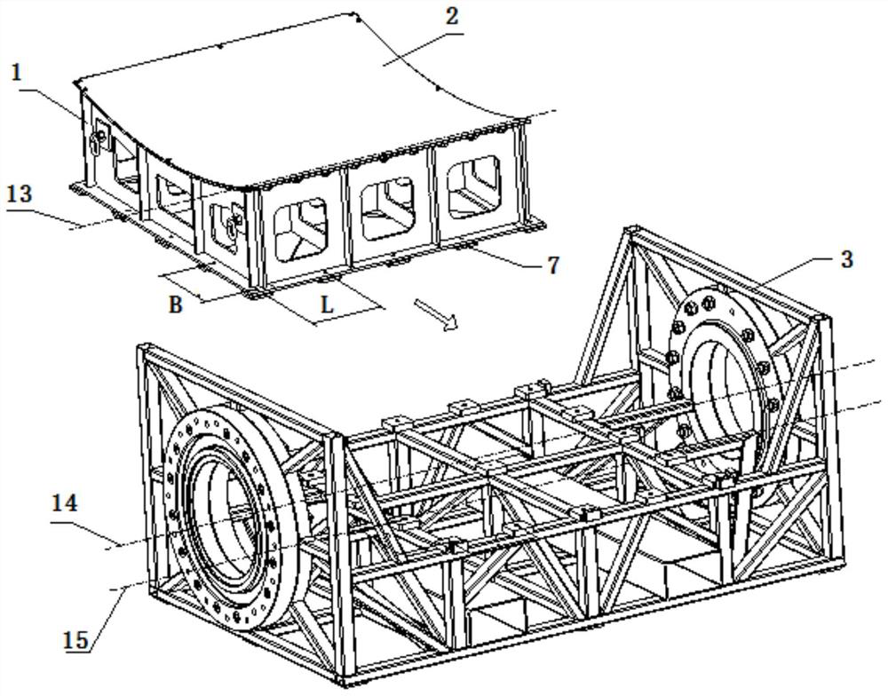
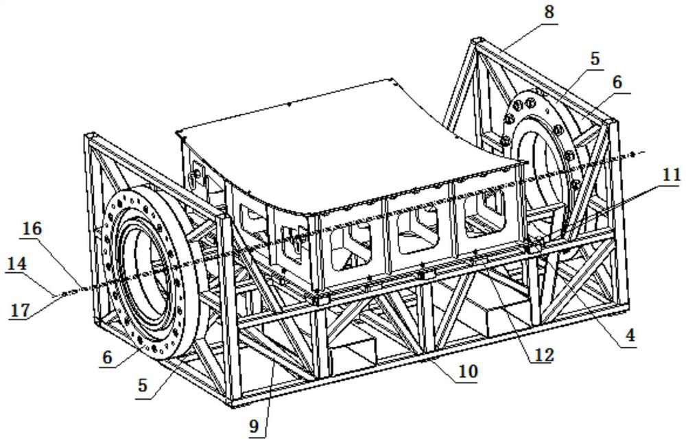
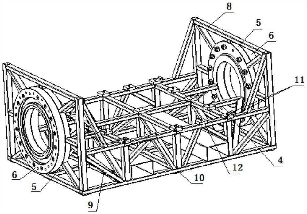
[0029] A composite material rotary laying device, comprising a ∪-shaped bottom frame 3, an adapter flange 5, and a flange 6. Two concentric transfer flanges 5 are fixed on both ends of the ∪-shaped bottom frame 3; two flanges 6 are respectively installed on the outside of the two transfer flanges 5; the ∪-shaped bottom frame 3 is provided with a support plane , the side of the support plane is provided with an initial positioning block 11 and fastener screws 4; the molding die 1 is placed on the support plane and fastened in the ∪-shaped bottom frame 3∪-shaped, forming an integral mold with two flanges After the disk 6 is tightly connected with the flange of the five-coordinate wire laying machine, the overall mold is driven up and down and rotated by the flange of the five-coordinate wire laying machine to complete the wire laying. The adapter flange 5 is provided with radial threaded holes and pin holes, and these threaded holes, pin holes are concentric with the correspondi...


PUM


Abstract

The invention discloses a composite material rotary fiber placement device and a use method. The composite material rotary fiber placement device comprises a U-shaped bottom frame, adapter flange plates and a flange plates. The two adapter flange plates and the two flange plates are arranged at the two ends of the U-shaped bottom frame respectively. The flange plate is fixedly connected to the outer side of the adapter flange plate; the forming die is mounted on the U-shaped bottom frame to form an integral die; the rotation axis formed by the integral die is overlapped with the central axis of the two flange plates or is within the required maximum tolerance range; the integral die and the five-coordinate fiber placement machine are clamped, a flange plate of the five-coordinate fiber placement machine drives the integral die to ascend, descend and rotate, and rapid and automatic fiber placement of the forming die is achieved. Through adjusting and installing the adapter flange plate, the form and location tolerance requirement of the U-shaped bottom frame is ensured; the assembly requirement of the five-coordinate fiber placement machine is ensured by adjusting the flange plate; the forming dies can be quickly exchanged and installed only by disassembling and assembling the screws; the U-shaped bottom frame has universality, so that more than 50% of rotary wire placement of the non-rotary body forming die is realized; and the production and economic benefits are improved.

Description

technical field [0001] The invention relates to the field of composite material molding auxiliary equipment, in particular to an auxiliary device suitable for composite material rotary wire laying and a use method. Background technique [0002] For the molding of composite material parts, wire laying is the premise and an important step. Machine wire laying replaces manual wire laying and brings various benefits. Using wire laying machine to lay wire must first install a fixed molding die. [0003] The three-coordinate wire laying machine lays composite material parts with flat or relatively gentle surfaces. The three-coordinate wire laying machine's wire laying head can be lifted and rotated, and the forming mold remains fixed after being installed on the auxiliary equipment. [0004] The new five-coordinate wire laying machine lays composite material parts faster and more effectively. When laying wire, the wire laying head of the five-coordinate wire laying machine radiall...

Claims


Application Information

Patent Timeline
Patent Type & Authority Applications(China)
IPC IPC(8): B29C70/38
CPCB29C70/382Y02T50/40
Inventor 肖光明曹文斌党晓丽洪晓明李静
Owner XI'AN AIRCRAFT INTERNATIONAL
Why Eureka
Try Eureka