Motor base tool and using method thereof

A technology of motor base and tooling, which is applied in the direction of manufacturing tools, positioning devices, metal processing equipment, etc., and can solve problems such as out-of-tolerance of verticality between the joint surface of the motor and the positioning notch, and out-of-tolerance of cylindricity

Active Publication Date: 2021-01-12
福建省威诺数控有限公司
View PDF13 Cites 0 Cited by
  • Summary
  • Abstract
  • Description
  • Claims
  • Application Information

AI Technical Summary

Problems solved by technology

[0006] In order to solve the problem of out-of-tolerance cylindricity of each hole in the workpiece processed by the motor base in the prior art and the out-of-tolerance problem of the perpendicularity between the joint surface of the motor and the

Method used


Image

  • Motor base tool and using method thereof
  • Motor base tool and using method thereof
  • Motor base tool and using method thereof

Examples


Embodiment 1

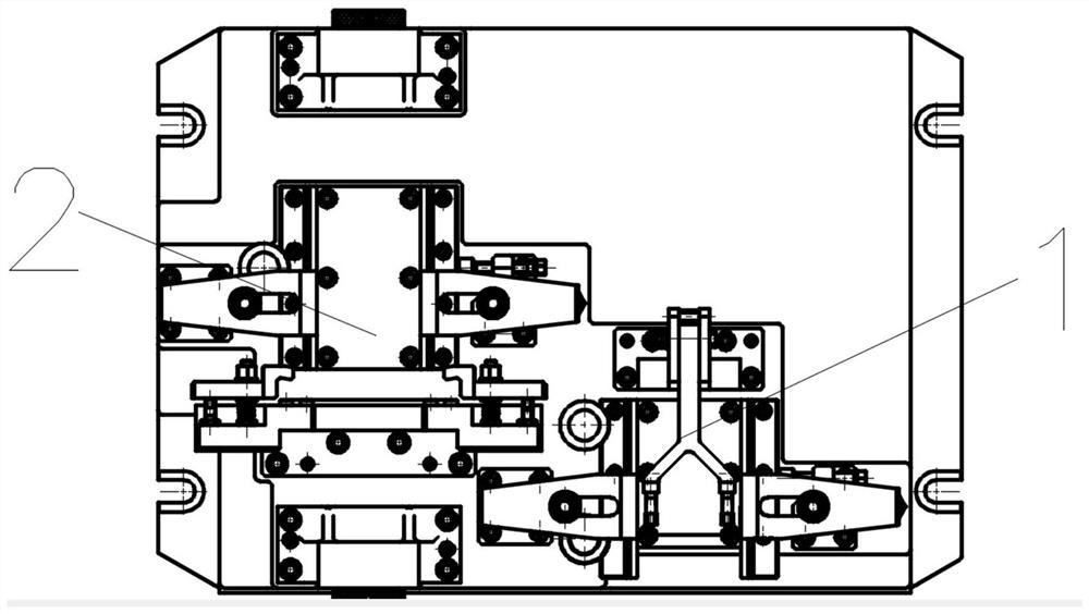
[0047] like figure 1 As shown, a motor seat tooling includes a rough machining tool 1 and a fine machining tool 2, and the rough machining tool 1 and the fine machining tool 2 are arranged on the frame with the same horizontal axis.

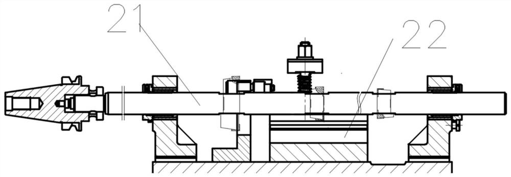
[0048] like figure 2 As shown, the finishing tooling 2 includes a boring part 21 and a tooling part 22 , the boring part 21 and the tooling part 22 are respectively arranged on the upper end of the frame, and the tooling part 22 is arranged inside the boring part 21 .

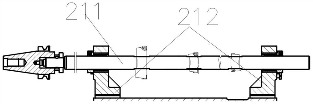
[0049] like image 3 As shown, the boring part 21 includes a boring tool 211 and a bracket 212 , and the boring tool 211 is arranged on the bracket 212 .

[0050] like Figure 4 As shown, the boring tool 211 includes a special connecting handle 2111, a tool bar 2112 and at least one boring blade 2113. The special connecting handle 2111 is arranged at one end of the tool bar 2112, and the boring blade 2113 is arranged at the middle part of the tool bar 2112. The upper part of ...


PUM


Abstract

The invention discloses a motor base tool and a using method thereof. The motor base tool is characterized by comprising a rough machining tool and a fine machining tool, wherein the rough machining tool and the fine machining tool are arranged on a frame and are provided with same horizontal axes; the fine machining tool comprises a boring part and a tool part; the boring part and the tool part are arranged at the upper end of the frame respectively; the tool part is arranged on the inner side of the boring part; the boring part comprises a boring cutter and a support frame; and the boring cutter is arranged on the support frame. Rough machining and fine machining processes are separated; a rotary cutting mode of a workpiece is changed into a fixed cutting mode; the original turning process is changed into a boring machining process mode; the single-cutter feeding of the boring cutter is not needed; the processing mode is changed into a semi-fine boring and fine boring machining modewhich is carried out by double support cutter rods and forming cutter plates; and the original machining process route is improved by completing machining of one process step through one-time cutter feeding.

Description

technical field [0001] The invention relates to the field of motor processing, in particular to a tool for a motor seat and a method for using the same. Background technique [0002] The original process of the motor seat: After rough and fine milling the motor handle joint surface, square outline, the joint surface of the bump stop block and the joint surface of the motor seat and the workpiece below on the milling machine, use special tooling to rough and fine turn all the workpiece on the lathe. Aperture. [0003] Because the lathe is a workpiece rotary cutting, the closer the mass center of the rotary body is to the spindle center, the better the machining accuracy. However, the motor seat is a casting, and there is a factor that the center of mass of the workpiece cannot be accurately determined. Therefore, the cylindricity of each hole will be out of tolerance in the workpiece after processing. Over-tolerance and other issues. [0004] In order to improve the machin...

Claims


Application Information

Patent Timeline
IPC IPC(8): B23B39/00B23P15/00B23P23/02B23Q3/06
CPCB23P23/02B23P15/00B23B39/00B23Q3/06Y02P70/10
Inventor 金丽英柳晓川余乐烽林军佘智群
Owner 福建省威诺数控有限公司
Why Eureka
Try Eureka