Bracket for drying large-outer-diameter and high-thickness blanks and implementation method of bracket

A technology with large outer diameter and blank, applied in drying chamber/container, drying gas arrangement, drying, etc., can solve the problem of increased risk of product cracking or corner drop, slowing down air convection speed, large difference in blank moisture content, etc. problems, to achieve the effect of being easy to place or take out, increasing the speed of air convection, and speeding up the drying speed

Active Publication Date: 2022-02-15
HENGDIAN GRP DMEGC MAGNETICS CO LTD
View PDF6 Cites 0 Cited by
  • Summary
  • Abstract
  • Description
  • Claims
  • Application Information

AI Technical Summary

Problems solved by technology

[0005] 1. There are baffles around the existing wooden tray, which leads to the limited size of the inner lining, which does not match the size of the large blank, and slows down the speed of air convection, resulting in slow drying of the blank;
[0006] 2. There are m

Method used


Image

  • Bracket for drying large-outer-diameter and high-thickness blanks and implementation method of bracket
  • Bracket for drying large-outer-diameter and high-thickness blanks and implementation method of bracket
  • Bracket for drying large-outer-diameter and high-thickness blanks and implementation method of bracket

Examples


Embodiment 1

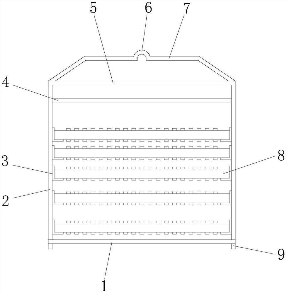
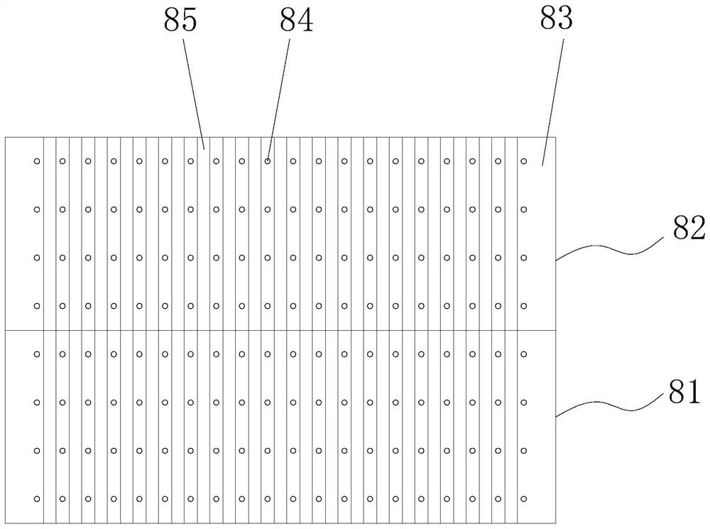
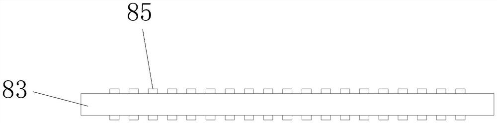
[0037] see Figure 1-3 , the present invention provides the following technical solutions: a large outer diameter and high thickness rough blank drying bracket, including a base 1, four corners above the base 1 are respectively provided with columns 2, the top of the column 2 is provided with a top seat 5, the top The top of the seat 5 is provided with a suspender 7, and the column 2 is provided with several layers of pallets 8. The pallet 8 includes a load-bearing plate 83. The load-bearing plate 83 is preferably a hard wood. The pad 85, the width, thickness and adjacent interval of the pad 85 are all preferably 1-1.5cm, and the present embodiment is preferably 1cm, and the pad 85 is preferably soft wood.

[0038] By adopting the above-mentioned technical scheme, the blank is supported by arranging several equally spaced pads 85 above the load-bearing plate 83, no more pads are needed, the speed of blank placement is accelerated, and the interval between the pads 85 is conduc...

Embodiment 2

[0042] This embodiment differs from Embodiment 1 in that: specifically, several through holes 84 are arranged at equal intervals between corresponding two adjacent pads 85 on the bearing plate 83, and the diameter of the through holes 84 is preferably 0.5-0.8 cm. An embodiment is preferably 0.6 cm.

[0043] By adopting the above-mentioned technical solution, the setting of the through hole 84 facilitates the convection of the upper and lower air, thereby further speeding up the drying speed of the blank.

Embodiment 3

[0045] The difference between this embodiment and Embodiment 1 lies in that: specifically, the lower part of the load-bearing plate 83 is provided with a pad strip 85 corresponding to the upper part.

[0046] By adopting the above technical solution, if heavy objects are placed on the wooden supporting board 8 in one direction for a long time, it is easy to cause the supporting board 8 to bend and deform downwards, which is not conducive to subsequent placement. Pad strips are provided on both sides of the load-bearing board 83 85. After using for a period of time, the blank can be turned over to place, so that the bending deformation of the supporting plate 8 can be avoided to a certain extent.


PUM


Abstract

The invention discloses a bracket for drying large-outer-diameter and high-thickness blanks. The bracket comprises a base, stand columns are arranged at the four corners of the upper portion of the base respectively, a top seat is arranged above the stand columns, a hanging rod is arranged above the top seat, a plurality of layers of supporting plates are arranged on the stand columns, each supporting plate comprises a bearing plate, and a plurality of filler strips are arranged above the bearing plate at equal intervals. The invention further discloses an implementation method of the bracket for drying the large-outer-diameter and high-thickness blanks. According to the blank drying device, the multiple filler strips are arranged above the bearing plates at equal intervals to support blanks, a cushion does not need to be placed any more, the blank placing speed is increased, air circulation is facilitated through the intervals between the filler strips, and therefore the blank drying speed is increased. The distances between the multiple layers of supporting plates are sequentially increased, the lower-layer air convection speed is increased, and therefore the drying speed of lower-layer blanks is increased, it is guaranteed that the drying speeds of the upper-layer blanks and the lower-layer blanks are consistent as much as possible, and the consistency of the water content of the blanks is guaranteed.

Description

technical field [0001] The invention belongs to the technical field of ferrite blank drying, and in particular relates to a bracket for drying blanks with large outer diameter and high thickness and a realization method thereof. Background technique [0002] The production and drying process of ferrite is the next process of the molding process. Before the large-scale and high-thick blank is taken out of the mold, the operator first places the prepared wooden tray on the operating table next to the press. Then place several or more than a dozen mats of the same thickness on the bottom of the wooden pallet according to a certain geometric shape. The mats are placed in the same direction, and the blanks are taken out from the press and cleaned, and then gently placed on the mats that have been placed regularly. On the top, after the bottom layer of the wooden support is full, place evenly distributed mats on the blank and continue to place the rough products, gradually filling...

Claims


Application Information

Patent Timeline
IPC IPC(8): B65D19/38B65D19/00F26B21/00F26B25/18B23K31/02
CPCB65D19/38B65D19/385B65D19/0053B65D19/0059F26B21/001F26B25/18B23K31/02
Inventor 杨跃红何震宇卢晓强张筝黄华为吴赛航
Owner HENGDIAN GRP DMEGC MAGNETICS CO LTD
Why Eureka
Try Eureka