
Device for disassembling and assembling gradient coil

A technology of gradient coils and support bases, applied in the direction of measuring devices, measuring magnetic variables, instruments, etc., can solve the problems of inability to disassemble, difficulty in installing and replacing gradient coils, and strong specificity, so as to achieve convenient movement and increase practicality. Performance and reliability, portability and storage

Pending Publication Date: 2022-02-15
UNITED IMAGING RES INST OF INNOVATIVE MEDICAL EQUIP
View PDF0 Cites 0 Cited by
  • Summary
  • Abstract
  • Description
  • Claims
  • Application Information

AI Technical Summary

Problems solved by technology

Although the ultra-high-field magnetic resonance system has greater clinical advantages due to its higher imaging quality, the weight of its gradient coils is usually as high as several tons, and the size is also larger, which limits the installation and replacement of gradient coils ( ie disassembly) brings great difficulty
[0004] In the prior art, the disassembly and assembly schemes of the gradient coils usually have the following types: For some small-volume low-field magnetic resonance systems, the gradient coils can be manually transported directly due to their relatively small weight and volume, without resorting to tool can move the gradient coil to complete the disassembly work; in some occasions where the installation site is large, large hoisting equipment such as cranes can be used to disassemble the gradient coil, but this method has great limitations and is only applicable to some Occasions: Design some special devices and use corresponding tooling for operation, but this method is highly specific, and often a tooling device is only suitable for disassembling and assembling a gradient coil
However, the above solutions are not suitable for the disassembly and assembly of gradient coils in ultra-high field magnetic resonance systems. For example, due to the large size and heavy mass of the gradient coils, the gradient coils are stuck inside the magnet and cannot be moved when they are half installed. or cannot be disassembled

Method used


Image

  • Device for disassembling and assembling gradient coil
  • Device for disassembling and assembling gradient coil
  • Device for disassembling and assembling gradient coil

Examples


Embodiment Construction

[0033] The following will clearly and completely describe the technical solutions in the embodiments of the present invention with reference to the accompanying drawings in the embodiments of the present invention. Obviously, the described embodiments are only some, not all, embodiments of the present invention. Based on the embodiments of the present invention, all other embodiments obtained by persons of ordinary skill in the art without making creative efforts belong to the protection scope of the present invention.

[0034] It should be noted that when a component is said to be "disposed on" or "installed on" another component, it may be directly on another component or there may be an intervening component. When a component is said to be "set on" another component, it may be set directly on the other component or there may be an intervening component at the same time. When a component is said to be "fixed" to another component, it may be directly fixed to the other compon...


PUM


Abstract

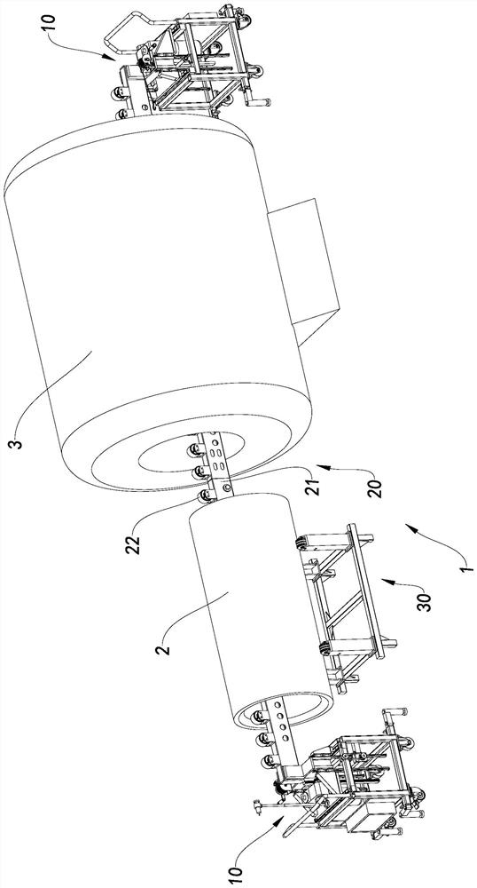
The invention relates to a device for disassembling and assembling a gradient coil. The device comprises a pair of supporting bases and a supporting guide rail, wherein the supporting bases are arranged at intervals, and the supporting guide rail is arranged on the supporting bases. The supporting guide rail comprises a pre-bending beam and a plurality of idler wheels, the idler wheels are rotatably arranged on the pre-bending beam in the length direction of the pre-bending beam, the pre-bending beam is arranged above the supporting bases in a supported mode, and the pre-bending beam hunches upwards relative to the supporting bases and is used for counteracting bending deflection generated by bearing the gradient coil, so that the load bearing levelness of the supporting guide rail is kept, and the situation that the gradient coil is stuck in the magnet and cannot move during disassembly and assembly is avoided.

Description

technical field [0001] The invention relates to the technical field of ultra-high field magnetic resonance, in particular to a device for disassembling and assembling gradient coils. Background technique [0002] Magnetic resonance imaging (MRI) is a commonly used, safe and ionizing radiation-free imaging optical inspection method in clinical practice, and it is widely used in medical and health care. As one of the core parts of the MRI system, the gradient coil is mainly used to provide alternating gradient magnetic fields in three directions for the MRI system, so as to realize the spatial positioning, phase encoding and frequency encoding of the imaged object, so its performance is good Damage will directly affect the imaging quality and imaging speed of the MRI system. [0003] At present, the basic components of the gradient coil generally include gradient coils in three orthogonal directions of XYZ, which generate gradient magnetic fields in the three directions respe...

Claims


Application Information

Patent Timeline
Patent Type & Authority Applications(China)
IPC IPC(8): G01R33/385
CPCG01R33/3858
Inventor 牛克佳
Owner UNITED IMAGING RES INST OF INNOVATIVE MEDICAL EQUIP
Learn More