Civil engineering building structure reinforcing device
What is Al technical title?
Al technical title is built by PatSnap Al team. It summarizes the technical point description of the patent document.
A technology of building structure and reinforcement device, applied in the direction of building structure, construction, building maintenance, etc., can solve the problems of lack of support, poor reinforcement effect, small applicability, etc., to achieve good applicability, improve practicability, and safety performance. high effect
Active Publication Date: 2022-02-18
CHENGDU UNIVERSITY OF TECHNOLOGY
View PDF23 Cites 2 Cited by
Summary
Abstract
Description
Claims
Application Information
AI Technical Summary
This helps you quickly interpret patents by identifying the three key elements:
Problems solved by technology
Method used
Benefits of technology
Problems solved by technology
[0003] The existing civil engineering building structure reinforcement device is mainly composed of right-angle steel and diagonal braces. When installing, firstly drill installation holes on the wall, then drive expansion nails into the installation holes, and then use nuts to connect the right-angle steel and diagonal braces. The formed reinforcements can be fixed on the expansion nails, but the structure of the reinforcements is fixed, not only is the applicability small, but also after installation, the reinforcements have no support for the building and require further deformation of the building to form Supporting force, that is, it can only be supported passively, but not actively supported, and the reinforcement effect is poor. At the same time, after disassembly, there will be reserved expansion nails protruding from the wall on the surface of the building, which is extremely unsightly. Therefore, it is urgent to design a civil engineering building Structural reinforcement
Method used
Image
Click on the blue label to locate the original text in one second.
Reading with bidirectional positioning of images and text.
Examples
Embodiment Construction
[0030] The technical solutions in the embodiments of the present invention will be clearly and completely described below in conjunction with the accompanying drawings in the embodiments of the present invention; obviously, the described embodiments are only some embodiments of the present invention; rather than all embodiments. Based on the embodiments of the present invention; all other embodiments obtained by persons of ordinary skill in the art without creative work; all belong to the protection scope of the present invention.
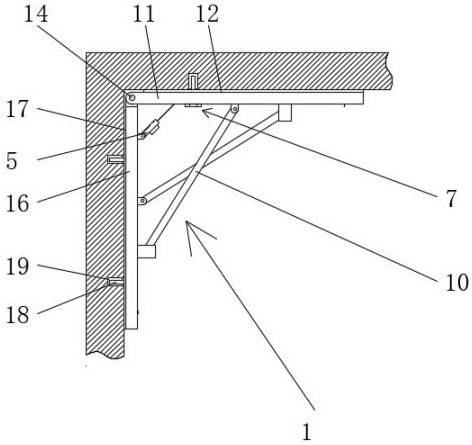
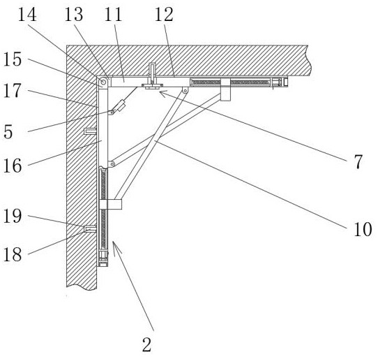
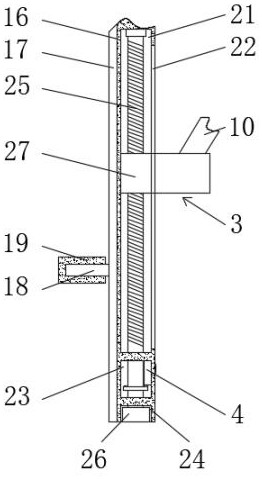
[0031] see Figure 1-10 , a civil engineering building structure reinforcement device, including a reinforcement assembly 1, the reinforcement assembly 1 includes an upper reinforcement plate 11, the top surface of the upper reinforcement plate 11 is fixedly connected with an upper reinforcement convex plate 12, and the left end of the upper reinforcement plate 11 is provided with The socket hole 13 is fixedly connected with a turning shaft 14 on t...
PUM
Abstract
The invention relates to a civil engineering building structure reinforcing device, which comprises a reinforcing assembly, the reinforcing assembly comprises an upper reinforcing plate, an upper reinforcing convex plate is fixedly connected to the top face of the upper reinforcing plate, and an inserting hole is formed in the left end of the upper reinforcing plate; through a limiting mechanism, people can adjust the inclination of the reinforcing inclined rod and the thrust of the reinforcing inclined rod to the upper reinforcing plate, traditional passive supporting is replaced with active supporting, the reinforcing effect is better, through the force fixing structure, the position of the limiting mechanism is fixed, then the inclination of the reinforcing inclined rod is kept unchanged, and through the monitoring structure, According to the civil engineering building structure reinforcing device, whether the civil engineering building structure reinforcing device deforms due to overlarge load or not can be detected in real time, through the monitoring mechanism, the monitoring structure gives out alarm sound under the condition that the civil engineering building structure reinforcing device deforms due to overlarge load, so that workers can take timely remedial measures, the safety performance is high, and the practicability of the civil engineering building structure reinforcing device is improved.
Description
technical field [0001] The invention relates to the construction field, and more specifically relates to a civil engineering building structure reinforcement device. Background technique [0002] Construction refers to the assets made by man-made construction, which belongs to the category of fixed assets, including houses and structures. Houses refer to engineering buildings for people to live, work, study, produce, operate, entertain, store goods and carry out other social activities. What is different from buildings are structures. Structures refer to engineering buildings other than houses, such as walls, roads, dams, wells, tunnels, water towers, bridges, and chimneys. A system composed of beams, slabs, columns, etc. that can withstand various actions. The so-called action refers to various factors that can cause internal forces and deformations of the system, such as loads, earthquakes, temperature changes, and foundation settlements. During the use of time, due to fa...
Claims
Application Information
Patent Timeline
Application Date:The date an application was filed.
Publication Date:The date a patent or application was officially published.
First Publication Date:The earliest publication date of a patent with the same application number.
Issue Date:Publication date of the patent grant document.
PCT Entry Date:The Entry date of PCT National Phase.
Estimated Expiry Date:The statutory expiry date of a patent right according to the Patent Law, and it is the longest term of protection that the patent right can achieve without the termination of the patent right due to other reasons(Term extension factor has been taken into account ).
Invalid Date:Actual expiry date is based on effective date or publication date of legal transaction data of invalid patent.