Water pump installation structure of mop cleaning barrel

A mop cleaning bucket and installation structure technology, applied to cleaning equipment, cleaning machinery, carpet cleaning, etc., to achieve the effects of cost reduction, convenient assembly, and thorough cleaning

Pending Publication Date: 2022-02-22
NINGBO DERUNTANG INTELLIGENT TECH CO LTD
View PDF2 Cites 0 Cited by
  • Summary
  • Abstract
  • Description
  • Claims
  • Application Information

AI Technical Summary

Problems solved by technology

[0005] The above two patents have one thing in common, that is, the pump casing is formed by the joint connection of the upper casing and the lower casing. In order to make the product more competitive, how to reduce the cost as much as possible without reducing the product quality is the primary consideration of the enterprise. , how to reduce the consumables of the pump casing and the barrel, and reduce the cost of the mold is a technical problem to be solved by those skilled in the art

Method used


Image

  • Water pump installation structure of mop cleaning barrel
  • Water pump installation structure of mop cleaning barrel
  • Water pump installation structure of mop cleaning barrel

Examples


Embodiment Construction

[0025] The present invention will be further described in detail below in conjunction with the accompanying drawings and embodiments.

[0026] Such as Figure 1~6 Shown is a preferred embodiment of the present invention.

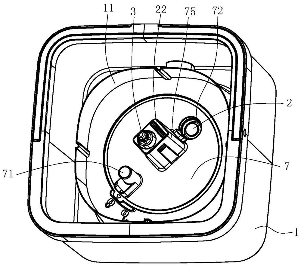
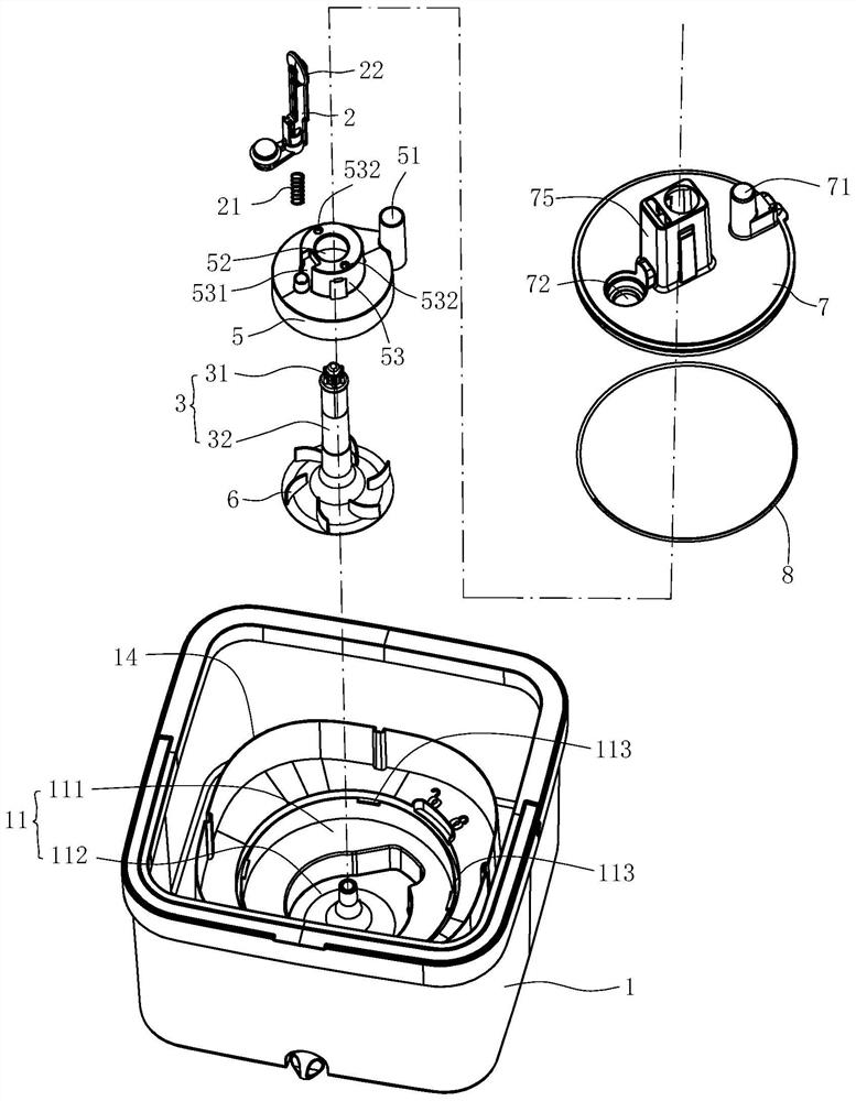
[0027] A water pump installation structure for a mop cleaning bucket, including a bucket body 1, a transmission shaft 3, a wheel cover 5, and a pump wheel 6, the wheel cover covers the pump wheel 6, and the transmission shaft 3 passes through the perforation 52 on the wheel cover 5 Afterwards, it is coaxially connected with the pump wheel 6, and the power transmission shaft 3 is used to be connected with the mop head.

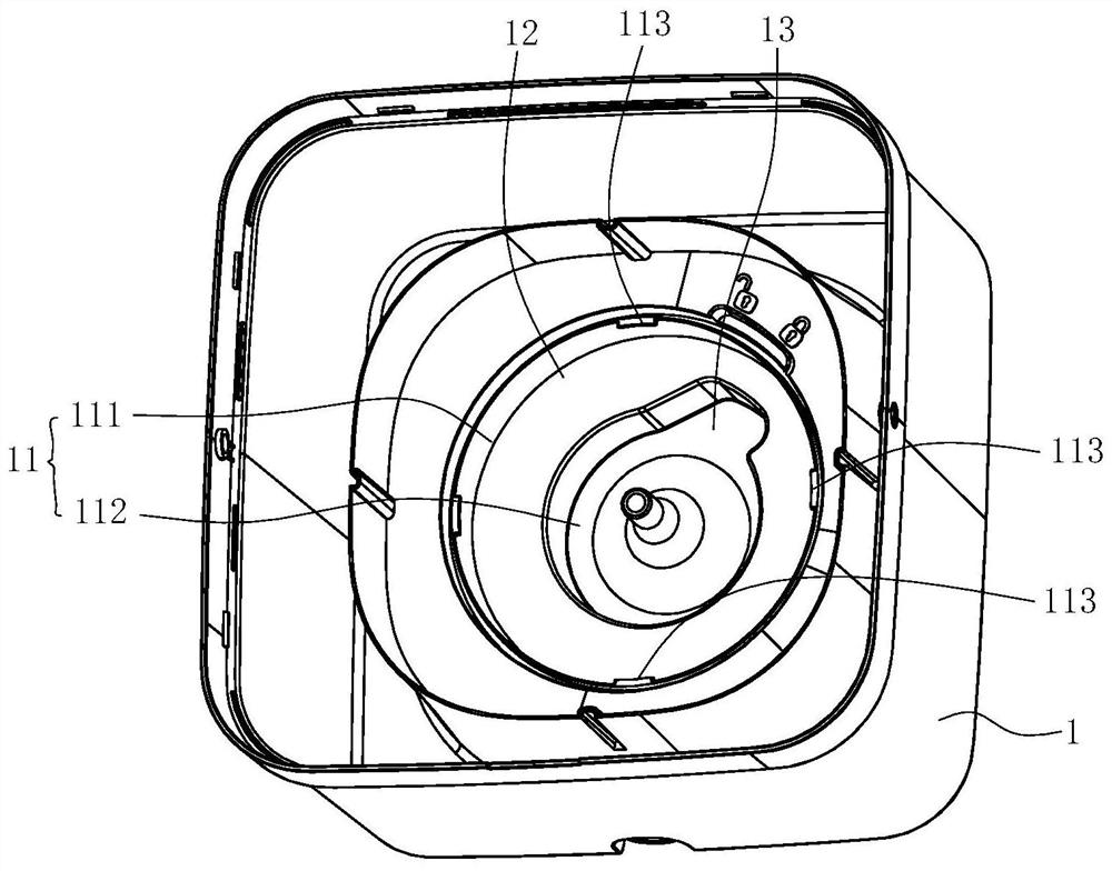
[0028] The bottom of barrel body 1 is provided with stepped cavity 11, and this cavity 11 is made of large cavity portion 111 and the small cavity portion 112 that is positioned at the big cavity portion 111 below, and pump wheel 6 and wheel cover 5 are all arranged on Inside the small cavity portion 112 . The mouth end cover of the large ...


PUM


Abstract

A water pump installation structure of a mop cleaning barrel comprises a barrel body, a transmission shaft, a wheel cover and a pump wheel, the pump wheel is covered with the wheel cover, and the transmission shaft penetrates through a penetrating hole in the wheel cover and then is connected with the pump wheel. The installation structure is characterized in that a step-shaped concave cavity is formed in the bottom of the barrel body, the pump wheel and the wheel cover are both arranged in the concave cavity, the opening end of the concave cavity is covered with a pump cover so that the concave cavity can form a clear water cavity, the transmission shaft upwards penetrates out of the pump cover, and a water spraying channel and a water supplementing channel which are communicated with the clear water cavity and the outside are formed in the pump cover. An inner cavity of the wheel cover is communicated with the water spraying channel in an inserted mode through a water outlet channel in the wheel cover, and the inner cavity of the wheel cover is communicated with the clean water cavity so that water can enter the inner cavity. The concave cavity is formed in the barrel body to serve as a lower shell in a traditional pump shell, one part is omitted, consumables are reduced, a pair of molds is omitted, and cost is effectively reduced.

Description

technical field [0001] The invention relates to a cleaning tool, in particular to a water pump installation structure of a mop cleaning bucket suitable for cleaning and dehydrating a hand-pressed rotary flat mop. Background technique [0002] The applicant has invented a non-lifting cleaning and drying barrel. The application number is CN201710332858.1 (publication number CN108852204A) and the invention patent application "Improved Mop Bucket" discloses such a water-saving mop bucket, including the barrel body, the barrel The body is provided with a support structure for supporting the mop tray, and the support structure can allow the mop tray placed on it to rotate at a fixed height position; it is characterized in that: the barrel body is also provided with a cleaning component and a water pump, and the cleaning component It is used to squeeze and scrape the wipes at the bottom of the mop pan rotating at a fixed height in the barrel. The water pump is used to spray water o...

Claims


Application Information

Patent Timeline
Patent Type & Authority Applications(China)
IPC IPC(8): A47L13/59
CPCA47L13/59
Inventor 不公告发明人
Owner NINGBO DERUNTANG INTELLIGENT TECH CO LTD
Why Eureka
Try Eureka