
Guide roller and method for manufacturing optical fiber

A manufacturing method and technology of guide rollers, which are applied in the field of guide rollers and optical fiber manufacturing, can solve problems such as increased rotation resistance, and achieve the effect of reducing the frequency of disconnection

Pending Publication Date: 2022-02-22
SUMITOMO ELECTRIC IND LTD
View PDF1 Cites 0 Cited by
  • Summary
  • Abstract
  • Description
  • Claims
  • Application Information

AI Technical Summary

Problems solved by technology

[0003] The rotation resistance of the guide roller may increase due to deterioration of the bearing, etc.

Method used


Image

  • Guide roller and method for manufacturing optical fiber
  • Guide roller and method for manufacturing optical fiber
  • Guide roller and method for manufacturing optical fiber

Examples


Embodiment Construction

[0013] [Description of Embodiments of the Present Invention]

[0014] First, the contents of the embodiments of the present invention will be described.

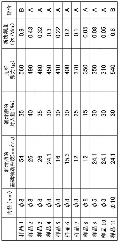
[0015] The guide roller according to the present invention is (1) a guide roller used in the manufacturing process of an optical fiber to guide a traveling optical fiber. Rolling elements rolling in the inner space of the bearing between the inner ring and the outer ring, the base oil dynamic viscosity of the grease sealed in the inner space of the bearing is 26mm at 40°C 2 / s below.

[0016] Set the base oil dynamic viscosity of the grease used in the bearing to 26mm at 40°C 2 / s or less, even when steel balls and grease are used, the rotational resistance of the roller can be reduced compared to a guide roller using grease with a base oil dynamic viscosity of the level used in ordinary bearings . Therefore, the frequency of disconnection of the optical fiber in the manufacturing process of the optical fiber can be redu...


PUM

PropertyMeasurementUnit
The inside diameter ofaaaaaaaaaa

Abstract

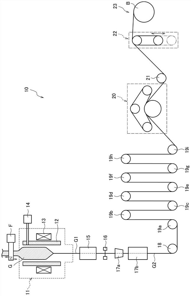
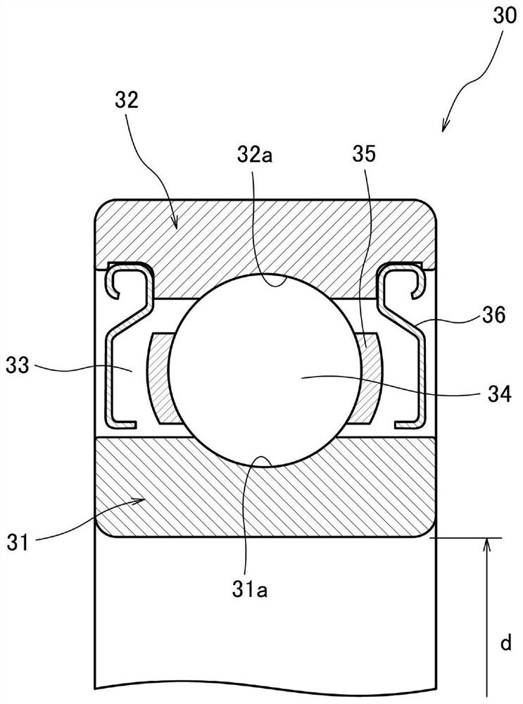
The invention provides a guide roller and a method for manufacturing an optical fiber, which can reduce the breaking frequency of the optical fiber in the manufacturing process of the optical fiber. The guide rollers (19a-19i) are used in a manufacturing process of an optical fiber and guide a traveling optical fiber. The guide roller is provided with a bearing (30) in the center. The bearing is provided with an inner ring (31), an outer ring (32), and rolling bodies (34) which are arranged in a bearing inner space (33) between the inner ring and the outer ring and roll. The base oil dynamic viscosity of the grease sealed in the bearing inner space is set to 26 mm2 / s or less at 40 DEG C.

Description

technical field [0001] The invention relates to a manufacturing method of a guide roller and an optical fiber. Background technique [0002] In a common optical fiber manufacturing (drawing) method, the tip portion of a glass base material for an optical fiber (hereinafter referred to as an optical fiber base material) is heated to soften it, and tension is applied to the softened portion to elongate it. Fine-diameter fiberglass. Next, through a cooling process, a resin coating process, etc., the optical fiber in which the glass fiber is covered by the cladding layer is obtained, and after being guided by a guide roller, it passes through the downstream side of the path (pass line) (when considering the direction of travel of the optical fiber). The rear side) is picked up by a pick-up device and wound on a bobbin or the like. [0003] In the guide roller, the rotation resistance of the roller may increase due to deterioration of the bearing or the like. When the number o...

Claims


Application Information

Patent Timeline
IPC IPC(8): C03B37/027C03B37/03C03C25/105
CPCC03B37/027C03B37/03C03C25/105
Inventor 冈崎岩吉川智井田惣太郎
Owner SUMITOMO ELECTRIC IND LTD
Learn More