Ramp rod box

A technology of drill pipe boxes and ramps, which is applied in the direction of drill pipes, drill pipes, earthwork drilling, etc., and can solve the problem that the drill pipe box cannot be used in rows of drill pipes, the drill pipe automatically fills the entire box body, and step-by-step loading, etc. problems, to achieve the effect of improving moving efficiency, shortening well construction period, and improving emission efficiency

Active Publication Date: 2022-04-05
山东胜油石油工程有限公司 +1
View PDF9 Cites 0 Cited by
  • Summary
  • Abstract
  • Description
  • Claims
  • Application Information

AI Technical Summary

Problems solved by technology

The existing drill rod box technology still has certain defects. Firstly, the drill rod cannot automatically fill the entire box body by loading it at one time, and needs to be filled step by step, which is inefficient; Rod seat use

Method used


Image

  • Ramp rod box
  • Ramp rod box
  • Ramp rod box

Examples


Embodiment 1

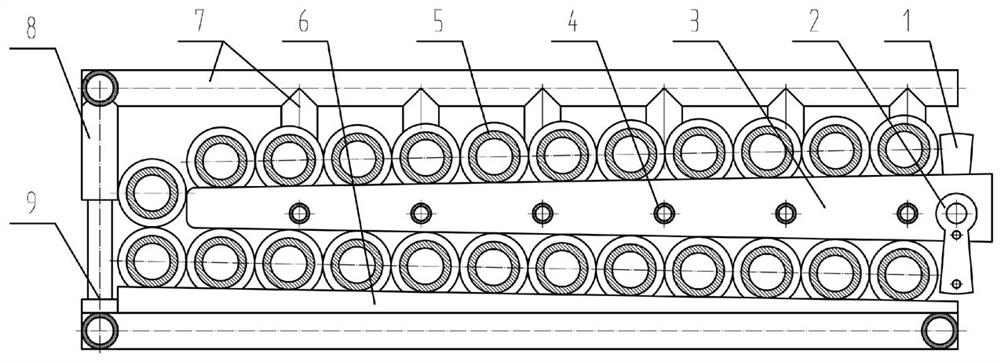
[0023] Embodiment 1, with reference to figure 2 with Figure 4 , the present invention provides a kind of ramp drill rod box, comprising end frame 7 and side frame 8, described end frame 7 and side frame 8 form main frame, one end of two end frames 7 is connected and fixed with side frame 8, two The other end of the end frame 7 is in an open state, and also includes an upper baffle 1, a lower baffle 2, a slant plate 3, a thin steel pipe 4 and a bottom slant plate 6, and a slant plate 3 is installed in the middle of the main frame, and the slant plate 3 Form a ramp with thin steel pipes 4, a plurality of round holes are evenly distributed on the slant plate 3, and a plurality of thin steel pipes 4 pass through it, and the two ends of the thin steel pipes 4 are movably connected with two end frames 7 respectively as cross arms; The lower side of the plate 3 is provided with a bottom inclined plate 6, the upper surface of the bottom inclined plate 6 is a slope structure, the up...

Embodiment 2

[0025] Embodiment 2, with reference to figure 1 with Figure 4 , the present invention provides the second type of ramp drill pipe box, which is different from Embodiment 1 in that: the side frame 8 and the movable frame 9 are connected by threads, and the position of the movable frame 9 can be adjusted to adapt to drill pipes 5 of various sizes. , also form the rolling channel of drill rod 5, in order to the smooth passage of drill rod 5 in the drill rod box on the left side, and the side frame 8 of embodiment 1 is fixed.

Embodiment 3

[0026] Embodiment 3, with reference to Figure 5 with Image 6 , the present invention provides the second kind of ramp drill pipe box, the difference from embodiment 2 is:

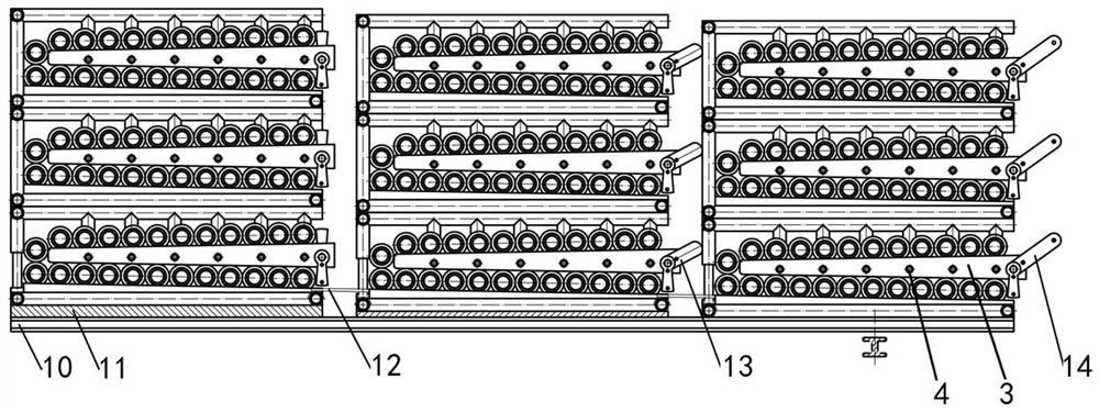
[0027] The lower stopper 2 of this embodiment adopts an outlet controller, and the outlet controller is composed of two groups of gear arms 15-1, handle 15-2, rotating rod 15-3, and fixed block 15-4. The two groups of gear arms 15 -1 and the handle 15-2 are welded on the rotating rod 15-3, and the two groups of gear arms 15-1 are arranged at right angles, the handle 15-2 is located at the other end of the two groups of gear arms 15-1, and the rotating rod 15 -3 is inserted in the circular hole of the fixed block 15-4, and the fixed block 15-4 is fixed on the thin steel pipe 4. When the handle 15-2 rotates, the rotating rod 15-3 and the gear arm 15-1 rotate together with it, because there are two gear arms 15-1, and there is an angle and span, the angle is when one of the gear arms 15 When -1 does not r...


PUM


Abstract

The invention relates to the technical field of oilfield drilling tools, in particular to a ramp drill pipe box. The technical scheme is: the bottom inclined plate, the end frame and the side frame form the main frame, the inclined plate is installed in the middle of the main frame, the inclined plate and the thin steel pipe form a ramp, and the bottom inclined plate is arranged on the lower side of the inclined plate. The upper surface of the bottom inclined plate is an inclined surface structure, an upper baffle is installed at the outer end of the inclined plate, and a lower stop is installed at the outer end of the bottom inclined plate, and a U-shaped structure is formed between the inclined plate and the inner wall of the main frame. The cavity, in which the drill rods are installed in sequence, is blocked by the upper baffle and the lower baffle. The beneficial effects are as follows: the present invention makes the drill rods in the drill rod box roll along the ramp under the action of its own gravity, so as to realize the function of sequential discharge; the coordinated use of multiple drill rod boxes can realize the sequential entry and exit of the multi-box drill rods one by one. The function of the ramp drill pipe box, therefore, the drill pipe box can be directly used as a drill pipe row seat, which can not only improve the work efficiency, but also effectively reduce the labor intensity of workers.

Description

technical field [0001] The invention relates to the technical field of oilfield drilling tools, in particular to a ramp drill pipe box. Background technique [0002] In the current petroleum industry, the commonly used device for the drilling team to place drill pipes on site is the drill pipe row seat. There are certain limitations in the use of the drill pipe row seat, which mainly includes two aspects: one is that the drill pipe is placed before being placed. , a crane or a pipe grabber is needed to lift the drill pipe to the drill pipe seat. In addition, when the drill pipe needs to be transported, a crane or a pipe grabber is needed again to lift the drill pipe on the drill pipe seat to the truck for transportation. In this way, there are low work efficiency, and multiple hoistings, to a certain extent, there are potential safety hazards; the second is that at least two field workers are required when the drill pipe is started drilling or the drill pipe is thrown after ...

Claims


Application Information

Patent Timeline
Patent Type & Authority Patents(China)
IPC IPC(8): E21B19/14
CPCE21B19/14
Inventor 李文波何亭徐建辉薛立国孙兆纯孙健何道宽高海波
Owner 山东胜油石油工程有限公司
Why Eureka
Try Eureka